
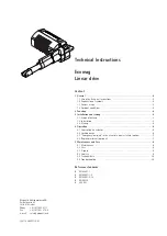


Technical Instructions
Linear drive Ecomag
Magnetic – The Linear Drives Company™
page 2/10
1
General
1.1
Using the Technical Instructions
The Technical Instructions are intended for designers or specialists who use the ECO-
MAG linear actuator in their products, and for fitters who work with the actuator. The
Technical Instructions contain all relevant information on this Magnetic product.
We reserve the right to make changes which are in the interest of technical progress.
Please read the Technical Instructions carefully and, above all, pay careful attention to
the Safety Instructions.
The Technical Instructions should be used for drawing up the User Manual for the end
product.
1.2 Explanation of symbols
The symbols opposite are used in the Technical Instructions to highlight possible dan-
gers and important notes.
1.3
Correct usage
The ECOMAG linear actuator has been designed for use in conjunction with the fol-
lowing Magnetic components:
SEM 1 control unit and
EHE handswitch
and is specifically intended for adjusting chairs and couches in medical and care sec-
tors.
Other uses must be discussed with Magnetic Liestal.
1.4
Ambient conditions
Operation:
Temperature
10 °C to 40 °C
Humidity
max. 85%
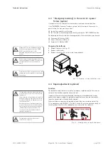
Storage / transport:
Temperature
-20 °C to 60 °C
Humidity
max. 95%
The unit is only suitable for indoor use and must not be subjected to the elements.
2
Function
ECOMAG linear actuators are DC actuators with worm gears and spindle units. The
gears convert the motor's rotational movement into a linear movement through the
threaded spindle's rotation being transferred to a pushing tube via a special nut.
The stroke is limited by built-in limit switches.
The power is supplied via an attachable or externally fitted SEM 1 control unit. The
control unit consists of a control box housing the transformer, the converter, up to 4
motor socket connections and a socket connection for the control device (e.g.
handswitch).
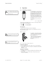
The linear actuator is operated using a control device (e.g. an EHE handswitch).
The feed speed is a function of the load!
The ECOMAG can be loaded with push forces (ECO 2/4/6/8) or pull and push forces
(ECO 3/5/7/9).
The maximum load on the actuator shown on the label refers to the centric push tube
axis.
A mechanical anti-pinching device for pull forces is fitted in the "push" versions. In
the "pull-push" versions, a mechanical anti-pinching device is available as an option.
The self locking of the actuator is at least equal to the push-/pullforce.
The maximum load specified on the label
must not be exceeded, since doing so will
mean that the prescribed level of safety will
not be provided.
The actuator may be destroyed if it is over-
loaded!
The ECOMAG linear actuator "push version"
(ECO 2/4/6/8) may only be subjected to com-
pressive loads. If pull forces are applied, the
push tube can disengage from the outer tube.
Risk of accident!
This symbol is used to indicate operations and
states which could endanger life and limb.
Follow the instructions precisely!
This symbol provides the user with useful
information.
This actuator must not be operated in
potentially explosive atmospheres.
L5311,2400E.1/12.03


