


14
CHAPTER 5
DELIVERY AND ASSEMBLY
5.1
CHECKING THE MACHINE
ON DELIVERY
All parts carefully checked before dispatch or deli-
very.
On
receiving
the machine,
ensure that it
not been damaged during transport. If damage has
occurred, contact the dealer concerned.
How the machine is lifted will depend on the model
and the type of packing. Details are given below.
The packing can vary from country to country de-
pending on transport requirements.
Lift the machine using a forklift truck, crane or oth-
er suitable equipment of sufficient capacity after
first checking the weight of the configurations in
the table given below.
Check the stability and positioning of the load on
the forklift truck forks or crane hook.
Keep the load as low as possible during move-
ment for maximum stability and to ensure that the
operator has maximum visibility.
If a forklift truck is used, ensure that the forks are
positioned as wide apart as possible.
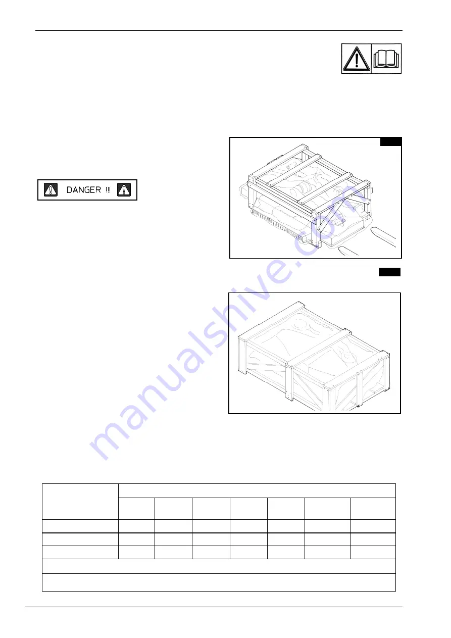
The manufacturer packages the machines accord-
ing to the following models:
Fig. 5.1: represents the standard packaging for
the lawn mower with rear grass ejector.
Fig. 5.2: represents the packaging for cart.
Packaging consists of a crate containing the load-
bearing frame, plus three pallets for the three
mowers. Alternatively, the three mowers can be packed in a single crate. The following table gives the weight
pallet for each mower, the weight of the frame (the machine without the mowers) and the gross weight of the
crate with the frame. The final column shows the weight of the three mowers when packed together in a sin-
gle crate.
PACKAGING TYPE
MACHINE WEIGHT KG-LBS
120
150
180
230
Machine
Cart
Fig. 5.12
Single crate
Fig. 5.1
178-390
208-455
239-525 310 – 685 SM/3600
SM/4500
SM/5200
* Weight of crated machine
** Net weight of one machine each model
5.1
5.2


