background image

SITECO Informatica s.r.l

.

via della Salute 14

40132 Bologna

Tel   051/6414470

Fax 051/400589

C.F.    04014680377

P. IVA 00689691202

[email protected]

http://www.sitecoinf.it

File rif. C:\Users\Administrator\AppData\Local\Temp\RSC_QuickStart _rev 2_99694.doc

Created 03.04.2017

Saved il 28.07.2017

Pag. 4 di 47

DO – 7.2 – 02 Rev. 0.2 del 20.01.2017

2.2 Installing the RS-C on a vehicle

The system must be installed on the roof of the vehicle (see section 3 for more details).

The vehicle on which to install the system must be equipped with transversal support bars applied on the

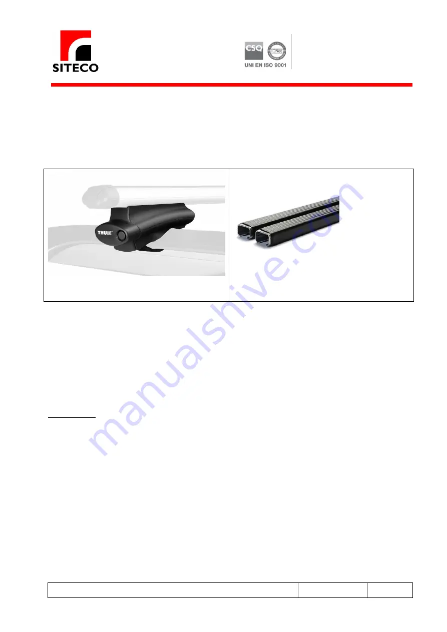
reels of the vehicle. There are several models on the market, but we recommend to use THULE 760 bars.

Thule 775 universal connectors

Transversal 760-769 Thule bars (30x20 mm)

Anyway, regardless of the brand choice, the sizes of the bars MUST definitely be the following:

30 mm width

20 mm height

length defined on the vehicle model

The RS-C can be mounted directly on the 2 Thule bars or on a special mounting frame expressly developed

using Misumi bars.

In the first case, the final distance between the two bars (measured from the middle of each bar) must be

exactly 31 cm in order to properly connect the system base.

To install the system on a Misumi Bar frame, see the next chapter.

Specific measures must be respected when installing the Thule bars on the vehicle roof, as described in
Section 4.

Summary of Contents for ROAD-SCANNER Compact

Page 1: ...oinf sitecoinf it http www sitecoinf it File rif C Users Administrator AppData Local Temp RSC_QuickStart _rev 2_99694 doc Created 03 04 2017 Saved il 28 07 2017 Pag 1 di 47 DO 7 2 02 Rev 0 2 del 20 01 2017 The Mobile Mapping System Powered by Faro ROAD SCANNER Compact Installation Guide and Getting started Manual v 1 0 March 2017 ...

Page 2: ...1 2017 Contents 1 INTRODUCTION 3 2 INSTALLATION 3 2 1 System Components 3 2 2 Installing the RS C on a vehicle 4 2 3 Misumi Bar Mounting Frame 5 2 4 Vehicle Model 6 2 5 Powering Set 8 2 6 Cable Connections 8 2 7 Wheel Specifications for DMI Mounting Fitment 10 3 SURVEY 11 3 1 Remote Connection to the RS C internal PC 11 3 2 Missions and Sequences 14 3 3 Starting a MISSION Logging 15 3 4 Starting a...

Page 3: ...sure to perform all the steps correctly WARNING The system is powered with a vehicle battery with minimum specification of 80 Ah and 12V According to the vehicle electric system alternator battery model the installation procedure can be slightly different For proper operations please refer to the manufacturer specifications of your vehicle battery 2 INSTALLATION 2 1 System Components Road Scanner ...

Page 4: ...he vehicle There are several models on the market but we recommend to use THULE 760 bars Thule 775 universal connectors Transversal 760 769 Thule bars 30x20 mm Anyway regardless of the brand choice the sizes of the bars MUST definitely be the following 30 mm width 20 mm height length defined on the vehicle model The RS C can be mounted directly on the 2 Thule bars or on a special mounting frame ex...

Page 5: ... same relative position between the two antennas in mounting and unmounting the system on different vehicles To facilitate this operation the system is provided with a dedicated mounting frame including commercial standard Misumi bars and sliders in aluminum see Figure 1 Figure 1 Misumi bar mounting frame The RS C mounting frame consists of the following components 2 bars 120x16 cm 2 Connection pl...

Page 6: ...in mind when choosing the vehicle for the MMS are the possible interferences of the laser beams of the laser scanner with the vehicle body To avoid blind angles during the survey and hence in the final production of the point clouds the laser scanners must not intercept the vehicle body For this reason some vehicle models are not suitable To choose the right vehicle the following points must be co...

Page 7: ...doc Created 03 04 2017 Saved il 28 07 2017 Pag 7 di 47 DO 7 2 02 Rev 0 2 del 20 01 2017 The back side of the vehicle must be flat as much as possible The vehicle must be large enough to carry the system during the mission transfers Suggested vehicle models Skoda Yeti Volvo XC90 Citroen Berlingo Volkswagen Touran After choosing the correct vehicle model make sure to install the Thule bars respectin...

Page 8: ...cle batteries provided by the customer Battery specifications AGM type 12 volts Minimum 80 Ah 2 6 Cable Connections To power the system some connection must be carried out The following steps are required to execute all the electrical connections Connect the vehicle battery to the Power Supply case using two specific positive and negative cables Connect the main power cable to the main power plug ...

Page 9: ...RSC_QuickStart _rev 2_99694 doc Created 03 04 2017 Saved il 28 07 2017 Pag 9 di 47 DO 7 2 02 Rev 0 2 del 20 01 2017 Connect the LAN cable to the system and the board laptop and activate the remote desktop connection with the RS C internal PC Install the Faro X130 laser scanner and connect the 2 relating laser cables All the connections mentioned above are shown in the following picture Figure 4 Ca...

Page 10: ...oc Created 03 04 2017 Saved il 28 07 2017 Pag 10 di 47 DO 7 2 02 Rev 0 2 del 20 01 2017 2 7 Wheel Specifications for DMI Mounting Fitment Please fill in the table below using millimeters as units of measure Vehicle Make Model and Year Number of Bolts per Wheel Lug Nut Size Wrench size Bolt Circle Diameter Rim Hub Clearance from base of lug nut Wrench Space Radius Lug Nut Size Wrench Size Wrench Sp...

Page 11: ...onics 6 Left laser switch on also the Left Laser scanner by pressing the start button on it 7 Right Laser switch on also the Left Laser scanner by pressing the start button on it 8 Start the board laptop computer and execute a remote connection with the RS C internal PC 3 1 Remote Connection to the RS C internal PC To create a remote connection with the PC contained in the Road Scanner C system fo...

Page 12: ...sitecoinf it http www sitecoinf it File rif C Users Administrator AppData Local Temp RSC_QuickStart _rev 2_99694 doc Created 03 04 2017 Saved il 28 07 2017 Pag 12 di 47 DO 7 2 02 Rev 0 2 del 20 01 2017 Figure 3 Pinging the RS C internal laptop If the ping is positive start a Remote Desktop connection using the IP 192 168 7 223 address ...

Page 13: ...Data Local Temp RSC_QuickStart _rev 2_99694 doc Created 03 04 2017 Saved il 28 07 2017 Pag 13 di 47 DO 7 2 02 Rev 0 2 del 20 01 2017 Figure 4 Remote desktop connection settings Enter the following credential to start the remote connection User ROADSCANNER Password SITECO At the end of the procedure the board laptop will establish the connection with the RS C internal PC showing its desktop see Fig...

Page 14: ...ed by Faro All the missions will be created logged using the Applanix LV Posview Software application The word sequence stands for a set of continuous sensor data and synchronization files All the sequences will be created logged using the SITECO Road Scanner Master Controller Software application WARNINGS 1 In terms of time a mission must be greater than a sequence since a mission must contain on...

Page 15: ...ministrator AppData Local Temp RSC_QuickStart _rev 2_99694 doc Created 03 04 2017 Saved il 28 07 2017 Pag 15 di 47 DO 7 2 02 Rev 0 2 del 20 01 2017 Figure 6 illustrates the points described here above Figure 6 Mission Sequence RINEX timespans 3 3 Starting a MISSION Logging To start a mission it is necessary to run the Applanix LV Posview Software Figure 7 Applanix LV Posview Main windows ...

Page 16: ...017 Pag 16 di 47 DO 7 2 02 Rev 0 2 del 20 01 2017 The AP20 inertial navigation system will be automatically connected Once the AP20 connection is established a window will show the IP address 192 168 53 100 At this point move the vehicle for a while for a short distance until the device status changes to Nav Full all the lights must become green To get the best GNSS signal conditions move to a goo...

Page 17: ...ocal Temp RSC_QuickStart _rev 2_99694 doc Created 03 04 2017 Saved il 28 07 2017 Pag 17 di 47 DO 7 2 02 Rev 0 2 del 20 01 2017 Once the system displays the Nav Full status the logging can start First Connect to the system pressing the connect button then Click on Logging Removable logging Media WARNING The dataset will be registered on the AP20 internal memory no further Removable Logging Media wi...

Page 18: ...07 2017 Pag 18 di 47 DO 7 2 02 Rev 0 2 del 20 01 2017 Press the POSPac button and manually enable the Event 1 Event 2 Event3 and Event 4 checkboxes Figure 8 Enabling Event 1 2 3 4 on LV Posview Logging WARNING The above step is mandatory Enabling the Event 1 2 3 4 is a prerequisite for synchronizing the sensor data If the relating checkboxes are not enabled the resulting survey could not be proces...

Page 19: ...307 in this example YYYYmmdd _A A for the first mission of the day B for the second etc Figure 9 Mission file naming convention Another naming example can be NYTectonic_20170324_B where B stands for the second mission of 24th of March carried out for Tectonic customer in NY After inserting the Filename press the Start Logging button The status must change to Writing WARNING At each survey check th...

Page 20: ...il 28 07 2017 Pag 20 di 47 DO 7 2 02 Rev 0 2 del 20 01 2017 3 4 Starting a SEQUENCE logging In order to start a SEQUENCE logging the operator must run the Road Scanner master Software by double clicking on the icon button When the Road Scanner Master starts a message will appear suggesting a folder name the last used folder where to store the data If the suggested folder is correct simply press th...

Page 21: ...2 02 Rev 0 2 del 20 01 2017 WARNING All the SEQUENCE raw data will be stored on a SSD hard disk This disk will be extracted from the RS C at the end of the survey and used to transfer the datasets to the PostProcessing PC once back in the office In the following example the unit assigned to the SSD disk is the letter D Press the OK button and access the Road Scanner master window To check the conf...

Page 22: ...6414470 Fax 051 400589 C F 04014680377 P IVA 00689691202 sitecoinf sitecoinf it http www sitecoinf it File rif C Users Administrator AppData Local Temp RSC_QuickStart _rev 2_99694 doc Created 03 04 2017 Saved il 28 07 2017 Pag 22 di 47 DO 7 2 02 Rev 0 2 del 20 01 2017 ...

Page 23: ...6414470 Fax 051 400589 C F 04014680377 P IVA 00689691202 sitecoinf sitecoinf it http www sitecoinf it File rif C Users Administrator AppData Local Temp RSC_QuickStart _rev 2_99694 doc Created 03 04 2017 Saved il 28 07 2017 Pag 23 di 47 DO 7 2 02 Rev 0 2 del 20 01 2017 ...

Page 24: ... C Users Administrator AppData Local Temp RSC_QuickStart _rev 2_99694 doc Created 03 04 2017 Saved il 28 07 2017 Pag 24 di 47 DO 7 2 02 Rev 0 2 del 20 01 2017 WARNING The laser IP address is relative to the Focus X130 position automatically provided with the system If you want to move one or both lasers it is necessary to fix this parameter according to the Laser configuration ...

Page 25: ...it File rif C Users Administrator AppData Local Temp RSC_QuickStart _rev 2_99694 doc Created 03 04 2017 Saved il 28 07 2017 Pag 25 di 47 DO 7 2 02 Rev 0 2 del 20 01 2017 At this point a sequence test is strongly recommended to check the system initialization phase Follow the steps indicated in the next pictures Press the Init Sequence button first button on the left ...

Page 26: ...itecoinf it http www sitecoinf it File rif C Users Administrator AppData Local Temp RSC_QuickStart _rev 2_99694 doc Created 03 04 2017 Saved il 28 07 2017 Pag 26 di 47 DO 7 2 02 Rev 0 2 del 20 01 2017 And confirm the action as required in the message boxes see the following windows Double check that the events are checked to be logged ...

Page 27: ...6414470 Fax 051 400589 C F 04014680377 P IVA 00689691202 sitecoinf sitecoinf it http www sitecoinf it File rif C Users Administrator AppData Local Temp RSC_QuickStart _rev 2_99694 doc Created 03 04 2017 Saved il 28 07 2017 Pag 27 di 47 DO 7 2 02 Rev 0 2 del 20 01 2017 ...

Page 28: ... 2017 Saved il 28 07 2017 Pag 28 di 47 DO 7 2 02 Rev 0 2 del 20 01 2017 Figure 10 Road Scanner Master is ready to start a Sequence logging After the completion of the Init Sequence step Figure 10 the dialog boxes will show the following All the lights in the left box will be bright green The lasers on channel 0 and 1 will be in Pause status To start the sequence logging press the Start Sequence bu...

Page 29: ... 7 2 02 Rev 0 2 del 20 01 2017 The lasers on channel 0 and 1 status will be Running The Ladybug camera has taken 1 image At this point the the sequence test procedure is completed If you got the results described here above the test has been successful and it is possible to start logging a real sequence To stop the test procedure do the following Press the Stop Button and click Yes in the message ...

Page 30: ...6414470 Fax 051 400589 C F 04014680377 P IVA 00689691202 sitecoinf sitecoinf it http www sitecoinf it File rif C Users Administrator AppData Local Temp RSC_QuickStart _rev 2_99694 doc Created 03 04 2017 Saved il 28 07 2017 Pag 30 di 47 DO 7 2 02 Rev 0 2 del 20 01 2017 ...

Page 31: ...ll be the first SEQUENCE relative to the _A mission and so on Adopting this naming convention allows you to easily recognize the correspondence between MISSIONS and SEQUENCES by simply looking at the filename In this way the following postprocessing operation or any remote support action during the data processing will be easier and quicker After choosing the SEQUENCE name it is necessary to selec...

Page 32: ...6414470 Fax 051 400589 C F 04014680377 P IVA 00689691202 sitecoinf sitecoinf it http www sitecoinf it File rif C Users Administrator AppData Local Temp RSC_QuickStart _rev 2_99694 doc Created 03 04 2017 Saved il 28 07 2017 Pag 32 di 47 DO 7 2 02 Rev 0 2 del 20 01 2017 ...

Page 33: ...6414470 Fax 051 400589 C F 04014680377 P IVA 00689691202 sitecoinf sitecoinf it http www sitecoinf it File rif C Users Administrator AppData Local Temp RSC_QuickStart _rev 2_99694 doc Created 03 04 2017 Saved il 28 07 2017 Pag 33 di 47 DO 7 2 02 Rev 0 2 del 20 01 2017 ...

Page 34: ... 04014680377 P IVA 00689691202 sitecoinf sitecoinf it http www sitecoinf it File rif C Users Administrator AppData Local Temp RSC_QuickStart _rev 2_99694 doc Created 03 04 2017 Saved il 28 07 2017 Pag 34 di 47 DO 7 2 02 Rev 0 2 del 20 01 2017 Press the Play button to start the SEQUENCE logging ...

Page 35: ...trator AppData Local Temp RSC_QuickStart _rev 2_99694 doc Created 03 04 2017 Saved il 28 07 2017 Pag 35 di 47 DO 7 2 02 Rev 0 2 del 20 01 2017 Figure 11 The system is Initialized and ready for the survey Once the RS C system is working it is ready to move Figure 11 then the vehicle can move and the survey session can start During the survey it is necessary to check Quality of acquired images ...

Page 36: ...691202 sitecoinf sitecoinf it http www sitecoinf it File rif C Users Administrator AppData Local Temp RSC_QuickStart _rev 2_99694 doc Created 03 04 2017 Saved il 28 07 2017 Pag 36 di 47 DO 7 2 02 Rev 0 2 del 20 01 2017 Figure 12 LadyBug5 Real Time view Quality of Positioning System by checking the GAMS solution status ...

Page 37: ... 04 2017 Saved il 28 07 2017 Pag 37 di 47 DO 7 2 02 Rev 0 2 del 20 01 2017 As a general rule if the lights referring to Attitude Heading Position and Velocity are green the mission is logging properly During the survey it is possible to assign a name to the trajectory that you are traveling see the panel Roads Start Road This action is not mandatory but can be useful However any name assigned duri...

Page 38: ... sitecoinf it File rif C Users Administrator AppData Local Temp RSC_QuickStart _rev 2_99694 doc Created 03 04 2017 Saved il 28 07 2017 Pag 38 di 47 DO 7 2 02 Rev 0 2 del 20 01 2017 During the survey the SEQUENCE acquisition can be paused by pressing the pause button and started again by pressing again the same button Figure 13 Sequence acquisition paused ...

Page 39: ...t File rif C Users Administrator AppData Local Temp RSC_QuickStart _rev 2_99694 doc Created 03 04 2017 Saved il 28 07 2017 Pag 39 di 47 DO 7 2 02 Rev 0 2 del 20 01 2017 3 5 Stopping a SEQUENCE logging When the survey in completed or if you need to stop the current sequence and start a new one the SEQUENCE acquisition can be stopped by simply pressing the stop button ...

Page 40: ...itecoinf it http www sitecoinf it File rif C Users Administrator AppData Local Temp RSC_QuickStart _rev 2_99694 doc Created 03 04 2017 Saved il 28 07 2017 Pag 40 di 47 DO 7 2 02 Rev 0 2 del 20 01 2017 Figure 14 SEQUENCE logging stopped The software application stops any connection with the positioning system and restore its idle status ...

Page 41: ...6414470 Fax 051 400589 C F 04014680377 P IVA 00689691202 sitecoinf sitecoinf it http www sitecoinf it File rif C Users Administrator AppData Local Temp RSC_QuickStart _rev 2_99694 doc Created 03 04 2017 Saved il 28 07 2017 Pag 41 di 47 DO 7 2 02 Rev 0 2 del 20 01 2017 ...

Page 42: ...ence while the MISSION continues to log If you need to start a new SEQUENCE follow the same procedure explained in section 3 4 Starting a SEQUENCE logging note that if you use _A2 as a name you do not need to run a TestSequence procedure 3 6 Stopping a MISSION logging When the survey is completed also the MISSION logging must be stopped Make sure to park the vehicle with the system in an open area...

Page 43: ...400589 C F 04014680377 P IVA 00689691202 sitecoinf sitecoinf it http www sitecoinf it File rif C Users Administrator AppData Local Temp RSC_QuickStart _rev 2_99694 doc Created 03 04 2017 Saved il 28 07 2017 Pag 43 di 47 DO 7 2 02 Rev 0 2 del 20 01 2017 Click on the Stop Logging button ...

Page 44: ...AppData Local Temp RSC_QuickStart _rev 2_99694 doc Created 03 04 2017 Saved il 28 07 2017 Pag 44 di 47 DO 7 2 02 Rev 0 2 del 20 01 2017 The Positioning System status changes to Idle 3 7 Positioning System Data Download The Applanix AP20 raw data are stored in the internal storage memory To download the data from the internal memory to the SSD it is necessary to use an FTP connection Start FileZill...

Page 45: ...ocal Temp RSC_QuickStart _rev 2_99694 doc Created 03 04 2017 Saved il 28 07 2017 Pag 45 di 47 DO 7 2 02 Rev 0 2 del 20 01 2017 Select the poslv button on the left top corner of the Remote Desktop Connection window The AP20 internal memory files will be listed on the right window Select all the files relative to the logged MISSION in the example above PONTI_20170307_A 150 149 148 etc and move them ...

Page 46: ...ed 03 04 2017 Saved il 28 07 2017 Pag 46 di 47 DO 7 2 02 Rev 0 2 del 20 01 2017 and dropping to the left window in the Position subdirectory of the working directory in our example D PONTI_20170307 Position Once the file transfer is completed stop the Applanix AP20 To do this go back to the LV Posview application and click on Tools Shutdown Click Yes in the message box for shutting down and wait f...

Page 47: ...peration has been completed the Road Scanner C internal PC can be switched off To do this Click on Start Windows Security Shut Down Now the Survey is completed and the SSD storage disk can be extracted from the Road Scanner Compact This storage disk contains all the files apart from the optional GNSS Basestation RINEX requested for postprocessing Switch off the Left and Right Laser scanners by pre...

Reviews: