background image

4

3

2

1

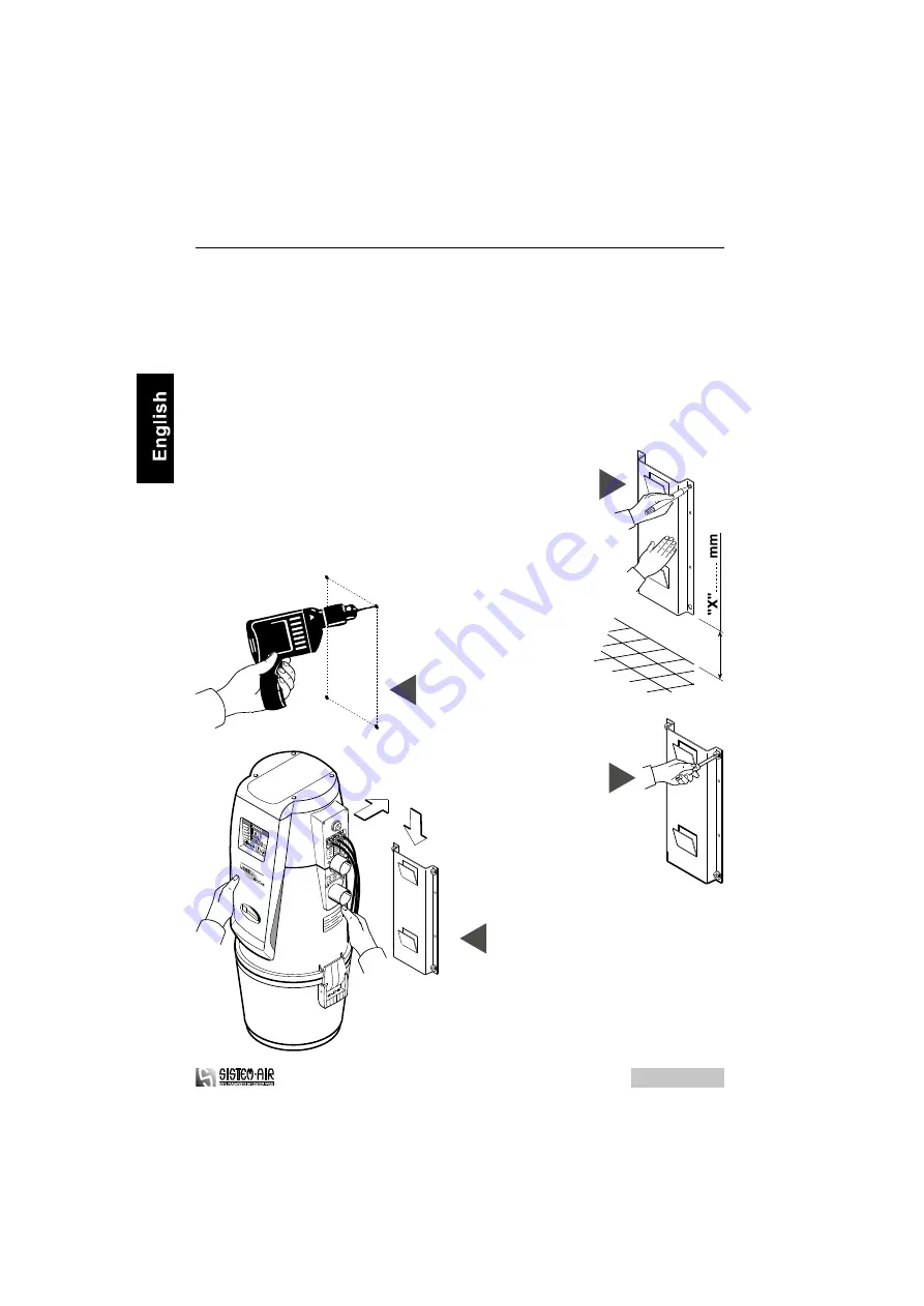
Hang the suction unit to the frame.

Position the special frame provided with the

suction unit and lay out the reference points.

(if the drilling has already been carried out, go to step 3)

Measure "X": Mod. TA/TE 050,100, 200, 400= Minimum 500 mm

Measure "X": Mod. TA/TE Mini, Media, Media Plus= Minimum 350 mm

Drill the holes into the wall.

Arrange the frame on the wall.

4.3 Installation of the central suction unit

You  must  use  the  special  frame  (provided  with  the  suction  unit)  and  the  special

screws  to  hang  the  central  suction  unit  firmly  and  permanently  to  a  wall.

Remember  that  the  suction  unit  must  hold  up  the  equivalent  of  eight  times  the

weight of the suction unit (please refer to par. 3.5 table).

The operator must hang the suction unit at a suitable distance from the floor to allow

an easy unloading of the dust container and a trouble-freer replacement of the filter.

Follow the instructions detailed herebelow to hang correctly the suction unit to the wall:

TA-TE 02/04-01

16

Installation, use and maintenance guide

Summary of Contents for 3107.0TA

Page 1: ...the pipe network 17 4 5 Electric system 18 5 How to use the central suction unit 5 1 Starting of the suction unit 19 5 2 Use of the suction unit 19 6 Maintenance 6 1 Programmed maintenance 20 6 2 Unl...

Page 2: ...ction unit when it is working and never let the children play with the suction inlets or with the suction unit Unplug the central suction unit when The power supply cable is worn out or damaged The ce...

Page 3: ...of the central suction unit Technical Service Provider and After Sales Service Authorized Technical Assistance Center 1 3 Identification plate SISTEM AIR ITALY Tel 39 0381650082 Fax 39 0381650120 Typ...

Page 4: ...o move the suction unit to the location selected for the installation If necessary use a trolley to move the suction unit or ask somebody to help you Arrange the cardboard box on the floor with the op...

Page 5: ...the straps Remove the upper cardboard protection lift the suction unit and arrange it on the floor in a vertical position Remove the dust protection bag Take out all the accessories contained in the...

Page 6: ...the Builder s trademark One user guide for correct installation use and maintenance One exhaust silencer made of plastic for the air exhaust 6 Installation use and maintenance guide Check that the suc...

Page 7: ...ion hose The SISTEM AIR central suction unit must be installed in a separated room for example in a storage room in a garage or in another service room and is connected to the suction pipes network Th...

Page 8: ...ge 3 3 Compliance with the requirements and the relevant provisions of the EEC Directives in force The suction units model SA which are the object of this user guide fully comply with the requirements...

Page 9: ...Activa Line are equipped with computers which control the maintenance cycles and indicate when it s time to carry out maintenance operations Soundproofing top cover Electronic card supporting panel Po...

Page 10: ...3 5 Technical features See picture and table 10 Installation use and maintenance guide TA TE 02 04 01...

Page 11: ...11 TA TE 02 04 01 Installation use and maintenance guide...

Page 12: ...to carry out motor servicing 6 key It is used during programming operations to increase the value indicated on the display 7 key It is used during programming operations to decrease the value indicat...

Page 13: ...o be installed in a multistorey building the suction unit must be located at the lowest level of the building The suction unit can be installed in a service room for example in a garage or in a storag...

Page 14: ...m DX right to SX left model The suction units included in the TECNO line are usually delivered suction and exhaust pipes connections assembled on the right side of the unit DX model when necessary it...

Page 15: ...uide Fix the adhesive plate supplied with the central suction unit 7 6 5 8 Plug the card cable in the special guides and assemble the dustproof spongy disk to seal the opening Only for TECNO Activa Li...

Page 16: ...You must use the special frame provided with the suction unit and the special screws to hang the central suction unit firmly and permanently to a wall Remember that the suction unit must hold up the e...

Page 17: ...fitting to connect the suction unit to the suction hose Use the correct fitting to connect the suction unit to the air exhaust pipe Stick the silencer on the exhaust pipe near the exhaust grid 3 1 2...

Page 18: ...electric system not in compliance with the regulations in force Follow the instructions to carry out this operation correctly see picture Connect the starting signal input cable Connect the exit cable...

Page 19: ...of the hose in the suction inlet The suction system will start automatically 19 TA TE 02 04 01 Installation use and maintenance guide 5 HOW TO USE THE CENTRAL SUCTION UNIT After finishing the cleaning...

Page 20: ...n demand warns the user by means of a remote control system when it is necessary to carry out maintenance operations or connect directly to the service provider if a maintenance contract has been prev...

Page 21: ...al suction unit press the RESET key only for TECNO Activa Central suction unit Disassemble the dust container Remove the conveyor cone Unload the dust container Assemble the conveyor cone Reassemble t...

Page 22: ...RESET key only for TECNO Activa Central suction unit 6 3 Replacement of the filter cartridge Disassemble the dust container Unscrew the locking handle Replace the filter cartridge Screw the locking h...

Page 23: ...urface of the cartridge 7 SERVICING 7 1 Servicing criteria It is strictly forbidden to operate on the central suction unit to carry out any maintenance or servicing not mentioned and therefore not all...

Page 24: ...tion Modifying the values above is a very simple procedure but it requires a minimum of attention and all sequences should be followed meticulously in order to be effective If you need additional info...

Page 25: ...ne on 3 The led and will appear together with a bar on the monitor Now we are ready to enter the PIN 4 Press the button A will appear on the display 5 With the buttons choose the first number you wish...

Page 26: ...Press the button The led DUST CONTAINER UNLOADING ALARM will switch off and the led MOTOR MAINTENANCE ALARM will switch on On the display the number 1 will appear 18 With the buttons and choose a num...

Page 27: ...l switch on The programmed number of hours will be displayed see reference values at pag 23 5 DISPLAY OF THE DUST CONTAINER UNLOADING TIMING press the button The led will switch off and the led DUST C...

Page 28: ...see reference values at pag 23 4 CHANGE OF THE DUST CONTAINER UNLOADING TIMING Press the button until the DUST CONTAINER led switches on The programmed number of hours will be displayed Press buttons...

Page 29: ...ger human health or well being as well as the environment if handled improperly You must be acquainted with sites companies authorized to collect and dispose of used parts and materials The disposal a...

Page 30: ...uction system are obstructed The air exhaust is obstructed The microswitch of a single inlet does not work Possible corrective measures Plug in the power supply cable Press the start push button Plug...

Reviews: