background image

 61 93 556 D3509

105

D3509

.

201.01.02

.

02

19.09.2008

4 Operation 

Sirona Dental Systems GmbH

Assistant element 

Operating Instructions TENEO

4.6.7.2 

Connecting the Mini L.E.D.

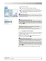
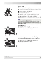
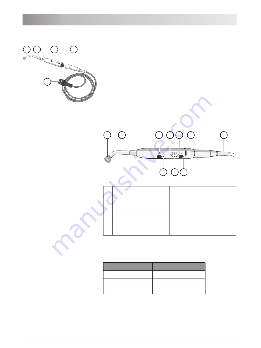
The Mini L.E.D. is connected to the assistant element in holder 1.

1.

Connect the supply cable 

(A)

 to the treatment center.

2.

Screw the hose coupling 

(B)

 onto the Mini L.E.D. 

(C)

.

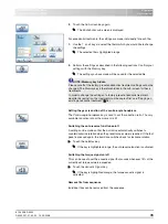
3.

Screw the sterilized light guide 

(B)

 onto the Mini L.E.D. 

(C)

. Make sure to 

insert the light guide correctly. 

ª

The light guide engages with an audible click.

4.

Slip the glare shield 

(E)

 onto the light guide 

(D)

.

ª

The glare shield protects your eyes against reflecting curing light

4.6.7.3 

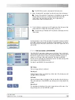
Functional description

Controls


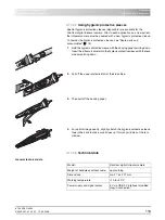
Status control lamp

The status control lamp 

(D)

 signals the following states:


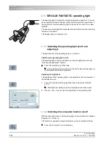
The Mini L.E.D. features three operating modes you can select with the 

Mode


button 

H

:

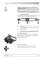
B

C

D

A

E

A

Glare shield

F

Pulse curing mode
lamp

B

Light guide 

G

"Soft start" mode lamp

C

On/off button

H

Mode button

D

Status control lamp

I

Handpiece

E

Quick curing mode
lamp

J

Supply cable

H

F

D

J

I

G

E

C

B

A

Status control lamp

Mode

off

Instrument deposited

green Normal 

operation 

red, flashing

Overheat protection 

Summary of Contents for teneo

Page 1: ...qbkbl l f b...

Page 2: ......

Page 3: ...2 Information on the unit 12 2 3 On site installation 12 2 4 Media quality 12 2 5 Maintenance and repair 13 2 6 Trouble free operation 13 2 7 Vacuum system 13 2 8 Patient chair 14 2 9 Ventilation slo...

Page 4: ...32 4 1 2 Switching the treatment center on off 32 4 1 3 Selecting a user profile 33 4 2 Control concept of touchscreen 34 4 3 Foot control 35 4 3 1 Wireless foot control 35 4 3 2 Operating the foot co...

Page 5: ...4 6 Assistant element 100 4 6 1 Maximum load capacity 100 4 6 2 Height adjustment 100 4 6 3 Positionability 100 4 6 4 Fixed keys on the assistant element 100 4 6 5 Suction handpieces 102 4 6 6 SPRAYVI...

Page 6: ...6 5 2 2 Disinfect the EasyTouch 137 5 2 3 Disinfecting handles 137 5 2 4 Disinfecting the tray 138 5 2 5 Disinfect clean and care for the upholstery 139 5 2 6 Disinfecting the MultiMotion headrest 139...

Page 7: ...hanging the battery of the wireless foot control 168 5 7 2 Changing the fuse of the external device connection 169 6 Maintenance by the service engineer 170 6 1 Inspection and maintenance 170 6 2 Safe...

Page 8: ...gs screen 186 11 5 4 Flushing settings screen 187 11 6 SIVISION program 187 11 6 1 SIDEXIS 187 11 6 2 PowerPoint 189 11 6 3 Media Player 189 11 7 Setup program 189 11 7 1 User interface 189 11 7 2 Dat...

Page 9: ...ned to assist you prior to initial use and whenever you require information later on We wish you much success and pleasure with TENEO Your TENEO Team 1 2 Contact data Customer Service Center Our Germa...

Page 10: ...ssories z SIROLUX FANTASTIC operating light z 19 flat screen monitor z HUGO dental working stool 1 5 Warranty and liability Warranty Passport To safeguard your warranty claims please complete the atta...

Page 11: ...and the relevant maintenance instructions 1 7 Formats and symbols used The symbols and character formats used in the present manual have the following meaning Instructions for action References Lists...

Page 12: ...ng water and dry oil free and hygienically clean air for the water and air supplies of the treatment center To ensure compliance with the medical and national legal requirements for water from treatme...

Page 13: ...al wear you as the system owner must have your system checked regularly by an authorized service engineer from your dental depot Furthermore safety checks must be performed Please contact your dental...

Page 14: ...tion Use only wipe disinfection in the vicinity of the ventilation slots 2 10 Intermittent operation The motors of the treatment center and of the treatment instruments are designed for intermittent o...

Page 15: ...nstallation process the requirements of IEC 60601 1 1 must be fulfilled 2 14 Electromagnetic compatibility Medical electrical equipment is subject to special precautionary measures regarding electroma...

Page 16: ...on Operating Instructions TENEO Dismantling Installation 2 16 Dismantling Installation Observe the installation instructions When dismantling and reassembling the system proceed according to the insta...

Page 17: ...vided the CSA mark is attached on the type plate The amalgam separator achieves a separation efficiency of 98 It therefore meets the requirements of the standard ISO 11143 and the German Institute for...

Page 18: ...ructions TENEO 3 2 System overview The treatment center comprises the following main components A Patient chair 19 B Motor driven headrest 19 shown here or MultiMotion headrest 2 20 C Foot control 21...

Page 19: ...tment 3 4 Headrest 3 4 1 Motor driven headrest The headrest allows for the following adjustment options z Motor driven extension retraction to adapt to the patient s stature z Motor driven tilting for...

Page 20: ...n headrest enables optimal access to the patient The following settings are possible z Retraction extension of the headrest extension to adjust the headrest to the patient s stature z Adjustment of he...

Page 21: ...ables hand free control of the treatment instruments Via the integrated cursor control virtually all functions of the treatment center can be controlled via the foot control as an alternative to hand...

Page 22: ...t control The power supply is provided by a battery 3 6 Dentist element All functions of the treatment center can be controlled via the EasyTouch control panel on the dentist element The dentist eleme...

Page 23: ...ndles left right C Touchscreen for display and operation D Fixed keys E Main switch F X ray viewer G Skid proof silicone mat H Additional holder for intraoral camera I Support arm height adjustable J...

Page 24: ...am operating mode Details on both operating modes see Simple Advanced Start program 44 Simple Start program operating mode left and Advanced Start program operating mode right Instrument program The I...

Page 25: ...ng Immediately moves the patient chair to a position for shock positioning of the patient Operating light Switches the operating light on off Light intensity 24 000 lux at 100 When the operating light...

Page 26: ...his function can be preset as a button or as a switch in the Setup program Freely selectable function freely available relay 230 VAC 6 A connected by the service engineer This function can be preset a...

Page 27: ...assistant s field of activity It can however also be positioned so as to enable unassisted treatment by the dentist A Holders 1 to 4 from left to right for instruments B Position of the hydrocolloid c...

Page 28: ...ssistant element Tumbler filling on off Flushing of the cuspidor bowl on off X ray viewer on off This key has no function on the version not equipped with an X ray viewer Timer function Triggers the t...

Page 29: ...nsity 8 000 lux Operating light on off Light intensity 24 000 lux at 100 3 8 Water unit The water unit is equipped with a disinfection system It adds a disinfectant to the water the patient comes in c...

Page 30: ...Additional devices connected to the external device connection are exposed to a hydrogen peroxide concentration of 0 1 0 2 If the additional devices are not suitable for the specified hydrogen peroxi...

Page 31: ...Instructions TENEO External device connection A Inlet connector with power supply max 6 A B Fuse for inlet connector 6 3 A slow blow C Quick coupling for water D Quick coupling for air Pressure Flow...

Page 32: ...enter thus features a power switch at the base of the chair and a main switch on the dentist element 4 1 2 1 Power switch The power switch connects the treatment center to the power supply During long...

Page 33: ...iple users can operate the treatment center without having to do without their own individual treatment and operation related settings The following is stored in the user profiles z Creation of chair...

Page 34: ...ogram z Instrument program z SIVISION program The selected program is highlighted blue If a symbol of a program change key is hidden the corresponding main program cannot be selected in the current op...

Page 35: ...ned sub screen immediately Settings screens In many cases functions not only can be switched on or off but also can be set If a function key is pressed and held 2 s the corresponding settings screen a...

Page 36: ...The wireless foot control is powered by a battery An almost empty battery is detected by the system and displayed in the footer The battery should then be replaced within a week to prevent system fai...

Page 37: ...mouth rinsing position S 9 An instrument motor turbine SIROSONIC TL is removed Press the left button Spray or NaCl is switched on off If the intraoral camera is removed the video still image is saved...

Page 38: ...ls for setting the cursor are used in the Setup program z Cursor control switched off The dentist element moves away from the user when the 4 way foot switch plate is pressed upward Counterclockwise o...

Page 39: ...ues see Operating the cursor control 39 The Clean key Setup routine and main switch cannot be accessed via the cursor control Orange and blue bars A blue bar indicates which functions are assigned wit...

Page 40: ...foot switch plate to the left or right Setting the intermediate values Move the 4 way foot switch plate to the left or right and hold it in this position The motor speed is displayed in the first lin...

Page 41: ...o IEC 60601 1 If the maximum load capacity is exceeded a risk of damage to the treatment chair and injury of the patient exists Never allow any persons who weigh more than 160 kg to sit on the patient...

Page 42: ...As long as a safety switch is activated the operation of the treatment center is restricted If a safety switch is permanently blocked please contact your service engineer 4 4 3 Triggering an immediat...

Page 43: ...90 for easier entry and exit 1 Press and hold the locking button behind the armrest The armrest is unlocked 2 Swivel the armrest toward the rear or toward the front The armrest automatically engages i...

Page 44: ...5 Simple Advanced Start program operating mode Function of the Start programs In the Start program you can select functions associated with movement of the patient chair Furthermore you also can acces...

Page 45: ...z Motor driven headrest z Treatment endodontics and implantology Furthermore the screens may vary due to individual Setup settings The following configurations may influence the Start programs see z...

Page 46: ...en Touch the Headrest in out keys Via the assistant element Press the Headrest in out fixed keys Via the 4 way switch Slide the upper 4 way switch upward or downward 4 4 6 2 Inclining the headrest The...

Page 47: ...atient s mouth 4 4 7 1 Patient height adjustment The headrest can be adjusted to the patient s height by pulling out or pushing in the headrest extension 4 4 7 2 Setting the jaw position The MultiMoti...

Page 48: ...bout the longitudinal axis of his body as well as lateral tilting of his head 1 Press one or both of the lateral releases A on the headrest The lock for rotational and tilt adjustment is released 2 Pr...

Page 49: ...ed via the touchscreen or via the user interface of the assistant element The entry exit and mouth rinsing positions can also be selected via the foot control You can individually reprogram the factor...

Page 50: ...n Touch the 0 key briefly 2 s Via foot control 9 All instruments are in place Press the right button of the foot control Via the assistant element Press the 0 key on the assistant element briefly 2 s...

Page 51: ...outh rinsing position key S is pressed again the treatment center returns to the previously set treatment position 9 The patient chair is located in any treatment position 1 Press the S key on the tou...

Page 52: ...described in the following sections 4 4 9 2 ErgoMotion Tilting the patient couch and inclining the backrest Compensated motion of the seat and backrest without any compression or stretching effects fo...

Page 53: ...ckrest This movement is particularly suitable for patients with limited mobility 9 The Manual Chair Adjustment screen or the Start program is displayed on the touchscreen in the Advanced Start program...

Page 54: ...ent on off 9 The Manual Chair Adjustment screen or the Start program is displayed on the touchscreen in the Advanced Start program operating mode 9 The Fine Adjustment key is displayed on the touchscr...

Page 55: ...ed state see Switching the SIROLUX FANTASTIC on off 4 Move the dentist element to the required position see Moving the dentist element 56 5 Press and hold the desired program key S 0 1 2 or if applica...

Page 56: ...e lumbar support to the patient s spinal curvature Touch the Decrease active lumbar support Increase active lumbar support keys 4 5 Dentist element 4 5 1 Maximum load capacity The maximum load of the...

Page 57: ...tion 50 9 The cursor control switched off 9 All instruments are in place Slide the 4 way foot switch plate upward The dentist element moves toward the foot end as long as the pedal is actuated 4 5 4 F...

Page 58: ...edge of the settings screen The selected timer is highlighted orange 3 Use the and keys to set the required time Increments From 0 05 to 1 00 5 s steps From 1 00 to 3 00 10 s steps From 3 00 to 9 30...

Page 59: ...see Creating chair programs and shock positioning 55 4 5 4 4 Operating light Operating light The light intensity of the operating light is 24 000 lux Switching the operating light on off The operatin...

Page 60: ...the Tumbler Filling fixed key The tumbler is filled with water for the preset time Pressing the Tumbler Filling fixed key again stops the filling function immediately Opening the settings screen Press...

Page 61: ...Setting the flushing time 1 Press and hold the Flushing key on the dentist element 2 s The Flushing settings screen appears on the touchscreen 2 Set the flushing time with the and keys Link flushing t...

Page 62: ...en quick setting keys and function levels If you use the Quick setting keys keys with five predefined motor speed values 0 09 40 x1000 rpm or intensity values 1 100 are displayed The values shown on t...

Page 63: ...ams The settings made in the Instrument program will be saved after the instrument is placed in its holder only if the Memory key was pressed beforehand 2 s After an instrument is removed the previous...

Page 64: ...ams will be opened when they are removed from the holders If more than one instrument is removed the screen of the instrument removed first is displayed Ball stopper Ball stopper A ball stopper for an...

Page 65: ...rument is removed from its holder Touch the key of the preselected coolant Spray Air or NaCl If the key of the preselected coolant is highlighted orange it will be switched on together with the instru...

Page 66: ...ted for lamps made by other manufacturers Setting the operating voltage 9 The Turbine Motor or Ultrasonic screen is displayed on the touchscreen 1 Press and hold the Setup fixed key 2 s The Setup prog...

Page 67: ...hlighted orange the speed foot control function is switched on 4 5 8 7 Setting the spray amount The spray amount is preset at the factory However it can be adjusted using the control valve at the bott...

Page 68: ...under any circumstances change the factory setting 5 Push the short end of the hose with the cannula through the stopper and into the NaCl bottle The regulator in the hose clip E must be completely op...

Page 69: ...surgical interventions The SL motor and the motors of the BL line all require separate control electronics It is not possible to combine collector and brushless motors Collector motor Collector motors...

Page 70: ...g at the hose and motor Additionally the motor couplings are color coded at the motor and hose BL motor The blue coded instrument hose BU must be used for the BL motor The BL motor is designed for dir...

Page 71: ...d value is less than the value displayed in the first line 0 5 s The selected speed is displayed in the first line in rpm revolutions per minute The quick setting keys are shaded gray for intermediate...

Page 72: ...chscreen 9 An electric motor is removed from its holder 9 The Motor screen is displayed on the touchscreen Touch the CCW Rotation key on the touchscreen For counterclockwise rotation The key is highli...

Page 73: ...nctional syringe The multifunctional syringe is used to clean the treatment areas and blow them dry It supplies preheated air and water media The heating cartridge is located in the handpiece 4 5 11 1...

Page 74: ...ter for the SPRAYVIT heating cartridge flows until the hose is completely filled The patient may be scalded by the emission of hot steam The heating cartridge can overheat and be destroyed After chang...

Page 75: ...off The air tempering can be switched off e g to check the sensitivity of the patient s teeth with cold air Touch the Air Temperature key If the key is highlighted orange the air tempering function is...

Page 76: ...it to different lamps Setting the operating voltage Use the and keys to adjust the operating voltage of the instrument light 4 5 12 SIROSONIC TL scaler The SIROSONIC TL scaler is used to remove plaqu...

Page 77: ...n percent in the first line Setting intermediate intensity values with quick setting keys 9 The SIROSONIC TL scaler is removed from its holder 9 The Ultrasonic screen is displayed on the touchscreen I...

Page 78: ...ty of the endodontics function is limited for safety reasons e g in order to prevent broken needles If instrument programs with quick setting keys are used values 1e to 5e will be assigned to the quic...

Page 79: ...d z Contact between the HF handpiece and metal implants or supraconstructions must be avoided z The active electrosurgical function can impair the function of other electronic devices z Check the elec...

Page 80: ...se intensity value is less than the value displayed in the first line 0 5 s The selected intensity is displayed in percent in the first line Intens The quick setting keys are shaded gray for intermedi...

Page 81: ...ent electrodes are available for this purpose The SIROTOM handpiece is a type BF applied part 9 The neutral electrode is plugged into the connection socket on the bottom side of the dentist element 1...

Page 82: ...ease the foot control The power of the electrosurgical handpiece is switched off Release the foot control before you deposit the HF instrument The programmed values of the previously selected user lev...

Page 83: ...lectrode is connected to the protective ground wire through a capacitor Maximum output voltage peak peak between handpiece and protective ground wire When cutting 1400 V At max coagulation 1600 V Modu...

Page 84: ...y the manufacturer is available for endodontic treatments The file assortment and sequence can be set by the user The treatment center allows for the management of two implantological and up to five e...

Page 85: ...burr drive from the instrument holder which is marked with an orange dot in the footer Depending on the type of treatment selected the Implantology Program or the Simple Endodontics Program is displa...

Page 86: ...ogical treatments The Assign burr drive display appears 2 Remove the burr drive you would like to use for the treatment type from its holder The Assign burr drive display automatically disappears The...

Page 87: ...key continues to flash If the burr drive is calibrated the key permanently remains highlighted orange The calibration is then completed 4 5 14 2 3 Setting the speed and torque In the Implantology func...

Page 88: ...n be switched on off by touching the NaCl key If the key is highlighted orange the pump can be activated by stepping on the foot pedal The NaCl flow rate set of the peristaltic pump is permanently dis...

Page 89: ...ting NaCl rinsing setting the flow rate and activating the rinse function 90 4 5 14 2 7 Saving settings The following settings can be saved for the selected work step in the Implantology program z For...

Page 90: ...n be set separately 9 The Preselect NaCl rinsing key is marked orange in the sub screen The setting keys for the NaCl rinsing are now displayed Use the and keys to set the flow rate for NaCl rinsing A...

Page 91: ...der the motor holder see Spare parts and consumables 174 The Implant motor becomes the active instrument as soon as the hose of the implantology instrument is connected to the dentist element Attachin...

Page 92: ...program is displayed on the touchscreen NOTE Cursor control The four keys that are marked with cursor positions blue orange can also be operated with the foot control NOTE Background shading of files...

Page 93: ...touched the next file system is displayed on the left side of the touchscreen 5 Select the file you would like to insert at the previously specified position from the list Touch the and keys Then conf...

Page 94: ...use the default file settings In the Endodontics function the speed and torque values of the contra angle handpiece and not those of the motor are specified The control electronics of the burr drive...

Page 95: ...n orange CCW arrow appears For clockwise rotation The CCW Rotation key is displayed gray and the orange CCW arrow disappears 4 5 14 3 6 Sub screen functions Opening the endodontics sub screen Opening...

Page 96: ...can be made so that the burr drive automatically switches to counterclockwise rotation when the preset torque value is reached If the foot pedal is pressed again the burr drive switches back to clock...

Page 97: ...er the endodontic treatment list z Create copy rename and if necessary delete endodontic treatments z Add specified file systems to the endodontic treatment list Opening the sub screen Opening the sub...

Page 98: ...me instead of creating a new endodontic treatment Then the settings can be changed This procedure allows for making changes to factory preset endodontic treatments without a pencil symbol 1 Touch the...

Page 99: ...dodontic treatment that you would like to delete The selected button is highlighted orange 2 Touch the Delete endodontic treatment key for more than 2 seconds The selected endodontic treatment is dele...

Page 100: ...height of the assistant element can be adjusted to achieve an ergonomic instrument height Please contact your service engineer 4 6 3 Positionability Collision with the assistant element 4 6 4 Fixed k...

Page 101: ...r coarse cleaning of the cuspidor bowl during treatment Press the Flushing fixed key The LED in the key lights up during the flushing function The flushing function is activated for the preset flushin...

Page 102: ...ng of composite fillings Press the Composite Function fixed key If the composite function is switched on the LED on the fixed key lights up on the assistant and dentist elements The light intensity of...

Page 103: ...itch at the base of the chair in any direction see Linking the spray aspirator to the 4 way foot switch 128 Saliva ejector A curved cannula that can be lodged in the corners of the mouth is provided f...

Page 104: ...ye lens disorders or have undergone eye surgery especially for gray cataracts must consult their medical eye specialist before using the light or undergoing treatment with the Mini L E D Caution is ad...

Page 105: ...gages with an audible click 4 Slip the glare shield E onto the light guide D The glare shield protects your eyes against reflecting curing light 4 6 7 3 Functional description Controls Status control...

Page 106: ...ini L E D is removed from its holder the operating mode last used before it was deposited is selected 1 Use the Mode key H to select the quick curing pulse curing or soft start mode The corresponding...

Page 107: ...ydrocolloid Two quick couplings with hoses 4 mm diameter are included in the scope of supply The impression tray can be ordered from a specialized dealer and connected to the hoses Connecting the hydr...

Page 108: ...quick couplings are engaged in the sockets Removing the hydrocolloid Hold the hose with one hand while you slide the snap on ring C upward with the other The hose is released and can be removed downw...

Page 109: ...ling the cuspidor bowl The cuspidor on the water unit can be manually swiveled approx 110 mm toward the patient chair A setting can be made that causes the cuspidor bowl to automatically move inward w...

Page 110: ...the tumbler filling function 60 Setting the filling level The tumbler filling level can be preset 1 Open the maintenance flap A on the base of the water unit 2 Set the filling level with the potentio...

Page 111: ...tly The tray can thus be subjected to different loads within limits without lowering its position Removing the instrument tray See Disinfecting the instrument tray 138 4 9 X ray viewer 4 9 1 Attachmen...

Page 112: ...touchscreen 9 The Start program is displayed on the touchscreen Touch the X ray viewer key If the key is highlighted orange the X ray viewer is switched on or the SIVISION monitor is switched to whit...

Page 113: ...the operating light on off The operating light is always switched on at the set brightness level see Adjusting the brightness below Press the Operating Light fixed key If the operating light is switch...

Page 114: ...us PC application must be installed to control the image arrangement from the treatment center For details refer to the manual Installation and Configuration of SIUCOM plus 4 11 1 SIVISION monitor 19...

Page 115: ...ital intraoral camera is a sensitive optical instrument and must always be handled with care Scratch sensitive lens window WARNING The patient can collide with the monitor The patient s head could col...

Page 116: ...ement Plug the connector of the intraoral camera into the correspondingly marked sockets on the dentist element The plug locks in place Removing the intraoral camera The plug of the intraoral camera i...

Page 117: ...t center For details see Communicating with SIDEXIS 120 When the intraoral camera is set down the live image window closes SIDEXIS remains active on the external PC Focusing the intraoral camera The S...

Page 118: ...old the hygienic protective sleeve with the backing paper pointing down Insert the intraoral camera into the hygienic protective sleeve with the lens window pointing down 2 Pull off the upper protecti...

Page 119: ...th the following PC applications z SIDEXIS z Microsoft PowerPoint z Windows Media Player The network connection of the treatment center must be configured in the setup program before using the SIVISIO...

Page 120: ...ange square is displayed communication with the PC application is not yet possible 4 12 1 2 Communication with SIDEXIS The SIDEXIS PC application enables you e g to display X ray and intraoral camera...

Page 121: ...displayed The image windows are arranged without overlapping Cascaded layout The opened windows are cascaded i e arranged slightly displaced behind one another All image window titles are thus visible...

Page 122: ...ng the overall definition of the image Undo The effect of the last filter operation is undone Restore original image The changes previously made e g via filters are canceled The most recently saved ve...

Page 123: ...functions can be individually configured via the Setup settings The treatment center can thus be adapted to match each user s personal method of treatment 4 13 1 Opening the setup programs 9 All inst...

Page 124: ...rmed via the Scroll forward back keys All of the settings you have made will be accepted when you leave the setup program 4 13 2 Configuring the EasyTouch user interface Touch the EasyTouch user inter...

Page 125: ...o set the brightness of the touchscreen 4 13 3 Setting the date and time Touch the Date and time key in the setup program The sub screen opens Setting the date The date is displayed in the format day...

Page 126: ...he backrest z Adjusting the chair height Chair program travel movements are always executed at maximum speed Touch the Fine Adjustment key If the key is highlighted orange the Fine Adjustment key is d...

Page 127: ...fied users can be selected after the treatment center is switched on Touch the User profiles key The selected field is highlighted orange The number of user profiles is limited to the set value If the...

Page 128: ...3 4 9 Linking the dentist element movement to chair programs A setting can be made to designate the chair programs for which the position of the dentist element can be additionally programmed z Field...

Page 129: ...y viewer key can change the SIVISION monitor to the white screen mode This function can be controlled only on the dentist element Touch the White screen key If the key is highlighted orange the X ray...

Page 130: ...aved One of the following presettings can be selected z Field 1 Quick setting keys with SaveMode z Field 2 Quick setting keys with DropMode z Field 3 Function levels Touch the Select memory type key T...

Page 131: ...iguration remains saved as an alternative You can toggle between the two configurations by switching the dynamic network configuration on and off see also Switching the dynamic network configuration o...

Page 132: ...0 0 0 0 9 The Network connection sub screen is displayed on the touchscreen 1 Touch the key at the end of the Gateway line The Gateway screen is displayed 2 Use keys 0 to 9 to set the first value oct...

Page 133: ...control on off key If the key is highlighted orange the network connection is switched on The SIVISION symbol is displayed on the program change key 4 13 6 4 Error message If a warning sign appears ab...

Page 134: ...ect and sterilize the treatment instruments 148 z Disinfect all handles 137 z Disinfecting the tray 138 z Care for and clean the operating light z Clean and disinfect the cuspidor bowl 155 Clean the g...

Page 135: ...16 16 16 Fax 49 0 62 51 16 18 18 Order No 59 70 905 5 1 3 Microbiological water test Perform the microbiological water test at regular intervals and after longer periods of disuse 1 week see also Med...

Page 136: ...30 seconds The cardboard disk with the nutrient medium will now absorb 1 ml of the water sample 5 Remove the tester from the container Shake out any excess water Empty the tank 6 Place the tester in t...

Page 137: ...on 3 Press and hold the Clean fixed key on the dentist element 3 s The touchscreen and fixed keys are now reactivated 5 2 3 Disinfecting handles Approved care and cleaning agents CAUTION Liquids can e...

Page 138: ...ent holder of the dentist element can be sprayed wiped and thermally disinfected See also Thermally disinfect the instrument holder of the assistant element 141 5 2 4 Disinfecting the tray The tray ca...

Page 139: ...tiMotion headrest The contact surface of the MultiMotion headrest can be removed to facilitate intensive cleaning and disinfecting if necessary Latching noses of head support CAUTION Approved care and...

Page 140: ...rasp underneath the instrument holder and raise it at the rear The instrument holder tilts to the front slightly and can be removed from the dentist element in an upward direction The removable silico...

Page 141: ...the assistant element The latch of the instrument holder is released 3 Remove the instrument holder The removable silicone mat on the assistant element can be sterilized Inserting the instrument holde...

Page 142: ...dual instruments are removed from their holders and held over the cuspidor bowl for purging The water lines of all removed instruments are then purged simultaneously It is also possible to purge the w...

Page 143: ...When all of the instruments have been deposited the purge program continues 9 The Remove instruments display appears on the touchscreen 1 Remove the instruments to be purged from the holder If an inst...

Page 144: ...t All of the instruments inserted in the sanitation bowl will be purged when the autopurge function is activated If the instruments remain in the sanitation bowl after the treatment center is switched...

Page 145: ...e Deposit instruments in instrument holders If the Deposit instruments display appears after the autopurge function has been started the treatment center has detected that not all of the instruments h...

Page 146: ...Remove the SPRAYVIT sleeves from the valve bodies the straight and contra angle handpieces from the water carrying instruments and the suction cannula from the spray aspirator 6 Insert the SPRAYVIT v...

Page 147: ...t possible the instrument concerned can be excluded from the purging process 1 Check the water flow through the instruments in the holders marked with a warning triangle on the touchscreen Set to maxi...

Page 148: ...s in the water lines will not increase excessively z Deposit instruments in instrument holders The autopurge function is completed Remove the instruments from the sanitation bowl and place them back i...

Page 149: ...mage replace the light guide since damage will impair its performance considerably 5 3 4 3 Cleaning disinfecting the SiroCam intraoral digital camera Due to its shape the SiroCam digital intraoral cam...

Page 150: ...ove the cotton wool roll 2 Insert a new cotton wool roll 3 Push the cup up again 5 4 Vacuum system 5 4 1 Purge the vacuum system To ensure that the vacuum system is always ready for use you must aspir...

Page 151: ...uum system The vacuum system is subjected to septic secretions saliva and blood daily Disinfection at regular intervals is therefore absolutely mandatory for hygienic reasons Approved care and cleanin...

Page 152: ...g adapter B Cleaning procedure 1 Pour 1 liter of cleaning and disinfectant solution into the cuspidor bowl 2 Remove suction hoses D and E from their holders and attach them to the side of the cleaning...

Page 153: ...running water Filter inserts are inserted between the suction hoses and the assistant element to filter out solid particles Depending on the treatment involved it may also periodically be necessary to...

Page 154: ...y is performed in reverse order Grease the O rings A before reconnecting the suction hoses For grease see Care and cleaning agents Make sure that the suction hoses snap into place 5 4 5 Thermodisinfec...

Page 155: ...ment container must be emptied less often Amalgam residues 1 Remove the gold trap from the drain of the cuspidor bowl 2 Remove the amalgam residues from the gold trap Amalgam residues must be disposed...

Page 156: ...with a disinfection system It adds a disinfectant to the water the patient comes in contact with This reduces the amount of microorganisms in the water lines Germs in water lines When the supply of di...

Page 157: ...of the water filter B and or the air filter C 4 Check the filters and replace them if necessary 5 Reinsert the rubber ring E in the screw on cap B C Then plug on the filter D as shown in the drawing...

Page 158: ...and disinfecting the suction hoses 2 153 Fill the amalgam residues into the amalgam rotor 5 Hold the lower part of the amalgam separator upright Attach the transport cap to the amalgam rotor The tran...

Page 159: ...Document replacement of the amalgam rotor in the Amalgam separator operator s log D3521 Worldwide Perform documentation according to the relevant national regulations Amalgam separator operator s log...

Page 160: ...ses 2 153 Authorize a certified waste management company for this purpose Installing the sediment container 1 Grease the O ring C on the sediment container For greases see Care and cleaning agents 135...

Page 161: ...evice see Cleaning and disinfecting the vacuum system 151 Opening the chair sub screen Opening the sub screen 9 The Start program is displayed on the touchscreen Touch the Sub screen key The Start sub...

Page 162: ...clean the filter insert under running water in a sink not in the cuspidor bowl 4 Grease the O ring C of the filter insert For greases see Care and cleaning agents 135 5 Reinsert the filter insert in...

Page 163: ...strument holders Opening the sanitation screen via touchscreen 9 The Start program is displayed on the touchscreen 1 Touch the Sub screen key The Start sub screen is displayed 2 Touch the San key The...

Page 164: ...fectant If the Desinf display appears after the sanitation process is started the supply of disinfectant in the reservoir of the water unit is not sufficient to sanitize the treatment center Sanitatio...

Page 165: ...sert the adapter for the SPRAYVIT valve body C the instrument couplings D and the suction hoses E in the sanitation bowl as far as they will go 5 Insert the adapter for the saliva ejector hose F in th...

Page 166: ...t briefly until the water flow has been checked If sufficient water flow is present the treatment center continues with sanitation phase 3 Error message No water flow If the treatment center detects n...

Page 167: ...e that the treatment center is switched off for at least 24 hours but not longer than 3 days maximum sanitation time If necessary you can also switch off the power switch on the base of the treatment...

Page 168: ...Sanitation can be canceled during some sanitation phases e g if the treatment center urgently must be switched back on before the 24 hours have expired The Stop key shows whether cancellation is possi...

Page 169: ...d Assembling the foot control 1 Mount the switch part C on the foot control 2 Remove the screws A from the bottom of the foot control 5 7 2 Changing the fuse of the external device connection The inle...

Page 170: ...port Warranty Passport This document is part of the Maintenance Manual 6 2 Safety checks Medical equipment is designed in such a way that the first occurrence of a fault does not create a hazard to th...

Page 171: ...ation must be maintained for treatment centers with HF surgical equipment in Germany z Performance of safety tests z Personnel who have been trained in the use of HF surgical equipment 5 MPBetreibV z...

Page 172: ...wn by overheating The water in the tumbler filling unit is no longer heated Inform your service engineer 13 Battery of wireless foot control empty Operation of the treatment center no longer possible...

Page 173: ...internet access Remote access to your external PC is established via remote access software which must be installed on your PC Various different software applications can be used for remote access Pl...

Page 174: ...e navigation bar go to the menu items SERVICE Downloads and then open the document Care and cleaning agents If you do not have any access to the Internet you can order the list in one of the following...

Page 175: ...ers are sold by specialized dealers D rr Dental GmbH Co KG Postfach 1264 D 74302 Bietigheim Bissingen Order No 2106 010 50 500 pcs 2106 010 51 20 pcs Fuses Fuse for the external device connection 100...

Page 176: ...g an air conditioning system 0 35 kW Power consumption in the Standby mode 3 W Main building fuse 100 115 V AC 20 A slow blow 230 V AC 16 A slow blow Protection class Class I equipment Degree of prote...
Page 177: ...Relative humidity 10 95 Barometric pressure 500 hPa 1060 hPa Operating conditions Ambient temperature 10 C 40 C 50 F 104 F Relative humidity 30 85 no condensation Barometric pressure 700 hPa 1060 hPa...

Page 178: ...u item Entsorgung elektrischer und elektronischer Ger te Disposal of electric and electronic devices The form can either be downloaded or filled out online 2 Fill out the form with the corresponding d...

Page 179: ...tivated The time lapse is displayed in the footer of the touchscreen When the Timer Function key is pressed 2 s the Timer Function settings screen appears Shock positioning Immediately moves the patie...

Page 180: ...nel This is used to make sure that no unwanted functions can be accidentally triggered while cleaning the surface Setup key Used for individual configuration of the treatment center by the user and fo...

Page 181: ...lled Inclining the headrest if a motor driven headrest is installed ErgoMotion Tilting the patient couch and inclining the backrest Compensated motion of the seat and backrest without any compression...

Page 182: ...tment of cooling water flow for the cooling spoon Massage function Soft back massage Active lumbar support Adjustment of active lumbar support 11 3 Instrument program Speed quick setting keys Used to...

Page 183: ...nstrument see below Sub screen Used to access additional subordinate functions see the following function keys Preselect spray coolant Used to cool and rinse treatment areas Preselect air coolant Used...

Page 184: ...ram on the touchscreen Activating NaCl rinsing Rinses treatment areas with a sterile saline solution whenever the burr instrument stops as long as key is actuated Selecting a work step Used to select...

Page 185: ...dditional subordinate functions see the following function keys Setting the gear reduction of the contra angle handpiece Adjusts the gear ratio to match the contra angle handpiece being used Auto reve...

Page 186: ...en Timer keys Up to six timers can be set The maximum time setting is 9 minutes and 30 seconds Time loop If the key is highlighted orange the countdown will automatically be restarted when the set tim...

Page 187: ...led layout All open image windows are scaled to a uniform size in the display area and arranged without overlapping Full frame The active image window is enlarged so that it covers the entire display...

Page 188: ...on can be canceled by pressing the key once again Display image in pseudocolors To enable better distinction of image details an image can be displayed in a so called pseudo color mode The grayscale v...

Page 189: ...6 3 Media Player Start Media Player Media Player is started on the external PC The keys corresponding to the Media Player PC application are displayed on the right side of the touchscreen after a file...

Page 190: ...ly Chair program travel movements are always executed at maximum speed Simple Advanced Start program operating mode If the key is highlighted orange the Advanced Start program mode is selected Number...

Page 191: ...y chair program z Field 2 The position of the dentist element is not added to any chair program except for the mouth rinsing position S z Field 3 The position of the dentist element is added to every...

Page 192: ...osited in its holder the cooling spray remaining in the instrument head or in the tip of the instrument is automatically blown out by a brief activation of the chip blower air puff Spray temperature T...

Page 193: ...144 B Ball for instrument holder 64 140 Ball stopper 64 140 Bars orange and blue 39 Battery change wireless foot control 168 Bell key 61 129 Blasting device 13 Boost function 78 C Cal key 87 93 Calib...

Page 194: ...as und Wasserfaches 17 E E1 E2 62 130 EasyTouch user interface 14 24 34 124 137 Electric motor 69 Electromagnetic compatibility 15 Electromagnetic compatibility EMC 15 Electronic torque limitation 87...

Page 195: ...tray 107 Inertia of contra angle handpiece 87 93 Initial startup 32 Inserting a file in the sequence 92 Inserting an endo file in the sequence 92 Inspection and maintenance 170 Instrument holder 64 A...

Page 196: ...ological test 135 Mini L E D 104 149 Mini L E D curing light 104 Modulation type for HF surgery 80 Monitor 15 114 Motor aftercooling 130 Motor holder 91 141 Motor versions 69 Motor driven travel track...

Page 197: ...SIROSONIC TL scaler 76 SIROTOM 78 171 SIROTOM electrosurgical handpiece 78 171 SIROTOM HF electrosurgical handpiece 78 171 SIUCOM plus 114 119 SIVISION digital 15 114 149 Change to still live image 36...

Page 198: ...witch 32 Upholstery 139 USB port 123 Use of saline solution 67 User profile 33 127 Using the last position memory function 51 V Vacuum system 13 150 151 153 154 Ventilation hole 103 Ventilation slots...

Page 199: ......

Page 200: ...t K p a p d e OMMU p W m d aPRMVKOMNKMNKMOKMO NVKMVKOMMU KJk KW MMM MMM p a p d e rp W c PN SQSOR _ d K K p a p ii QUPR p a I p NMM I k OUOTP rp l k SN VP RRS aPRMV...

Reviews: