60 78 104 D 3488
14
D 3488.201.01.07.02
11.2009
4 Installation
Operating Instructions SIROEndo
NOTE
i
The plug-and-socket connectors are mechanically and/or color coded! There-
fore, make sure that the connectors are correctly oriented or have the match-
ing color when plugging them together.
13.
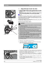
Connect the power supply (5) to the junction box (7) (secure connector
with bayonet ring).
14.
Connect the blue-coded foot switch (2) to the junction box (7) (connector
latches when plugged in).
15. Installation kit:
Fasten the junction box at a suitable location using the
adhesive strip included in delivery
and run the various cables using the
self-adhesive holders and cable ties.
16.
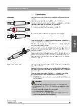
Carefully place the bottom part of the motor (C) onto the contact pins in
the motor (D). When doing this, make sure that the contact pins line up
with the sockets in the coupling. Now screw the bottom part of the motor
securely onto the motor.
17.
Connect the apex locator (6) to the bottom side of the SIROEndo (1).
18.
Connect the red-coded connector of the micromotor (3) to the bottom side
of the SIROEndo (1) (connector latches when plugged in).
19.
Connect the power supply (5) to the electric power outlet.
CAUTION
After attaching the SIROEndo to a support tube, check your treatment center
to make sure it is firmly fixed.
7
5
2
C
D
A/Rev
Reverse
Reduct.
System
Type
Torque
Rpm
Motor
Cal
Mem
Load
Save
SIROEndo
6
1
3


