background image

 63 22 668 D3561

4

D3561

.

021.01.06

.

02 12.2014

Table of contents

Sirona Dental Systems GmbH

Installation Requirements SINIUS / SINIUS CS / SINIUS TS

4.2

SINIUS CS dimensions, scale bar 1:20 ........................................................

26

4.2.1

Dimensions of the treatment room ...................................................

26

4.2.2

Side view..........................................................................................

27

4.2.3

Top view...........................................................................................

28

4.2.4

Top view with options.......................................................................

29

4.2.5

Size of the treatment room with HELIODENT Plus..........................

30

4.2.6

Side view with HELIODENT Plus.....................................................

31

4.3

SINIUS TS dimensions, scale bar 1:20.........................................................

32

4.3.1

Dimensions of the treatment room ...................................................

32

4.3.2

Side view..........................................................................................

33

4.3.3

Top view...........................................................................................

34

4.3.4

Top view with options.......................................................................

35

4.3.5

Size of the treatment room with HELIODENT Plus..........................

36

4.3.6

Side view with HELIODENT Plus.....................................................

37

4.4

Mounting plates.............................................................................................

38

4.5

Information on planning for the practice........................................................

40

4.6

Technical data...............................................................................................

41

4.7

Standards/Approvals.....................................................................................

44

5

Electromagnetic compatibility...................................................................................

46

5.1

Accessories...................................................................................................

46

5.2

Electromagnetic emission .............................................................................

47

5.3

Interference immunity....................................................................................

48

5.4

Working clearances.......................................................................................

50

5.5

Foot control wireless interface ......................................................................

51

6

Checklist...................................................................................................................

52

6.1

Installation site ..............................................................................................

52

6.2

Construction requirements ............................................................................

53

6.3

IT hardware ...................................................................................................

54

6.4

Network .........................................................................................................

55

6.5

Data processing ............................................................................................

56

Summary of Contents for Sinius

Page 1: ...f o NOKOMNQ pfkfrp L pfkfrp p L pfkfrp qp k W b Installation requirements...

Page 2: ......

Page 3: ...nstallation 9 3 1 Substrate floor 9 3 1 1 Load bearing capacity of the floor 9 3 1 2 Tensile forces 9 3 1 3 Stability 10 3 2 Connection to the public drinking water system 11 3 3 Media quality 12 3 4...

Page 4: ...4 3 1 Dimensions of the treatment room 32 4 3 2 Side view 33 4 3 3 Top view 34 4 3 4 Top view with options 35 4 3 5 Size of the treatment room with HELIODENT Plus 36 4 3 6 Side view with HELIODENT Plu...

Page 5: ...r regarding the necessary quality of the air and water supply media Information for the installer such as how to implement the connections for air water waste water suction air and the power supply In...

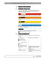
Page 6: ...DANGER An imminent danger that could result in serious bodily injury or death WARNING A possibly dangerous situation that could result in serious bodily injury or death CAUTION A possibly dangerous si...

Page 7: ...e user assumes the risk of using non approved accessories If any devices not approved by Sirona are connected they must comply with the applicable standards e g IEC 60950 1 for information technology...

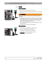
Page 8: ...er connection Installation Requirements SINIUS SINIUS CS SINIUS TS 2 4 Power connection WARNING Shock hazard It is essential that you switch off the power supply PRIOR to beginning the installation Th...

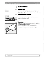
Page 9: ...se of an uneven floor the steel adapter plate must be used see Mounting plates 38 3 1 1 Load bearing capacity of the floor Load capacity The minimum load bearing capacity of the floor must be 0 5 N cm...

Page 10: ...eavy duty anchor bolts included with delivery 2 units are suitable for a clamping length A B of up to 100 mm Use 12 mm dia wall plugs but do not use wall plugs instead of heavy duty anchor bolts Use 1...

Page 11: ...s intrinsically safe according to the W540 worksheet and thus also complies with W270 and KTW Guideline on the use of plastics in contact with drinking water It can be connected directly to the public...

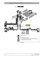
Page 12: ...a quality Description of media quality Water quality 1 bar 14 5 psi p 0 18 bar u 500 l min Wasserh rte Duret de l eau Water hardness Dureza del agua 1 4 mmol l 8 dH 80 m 0 08 mm 3 l min 2 5 bar p 6 0...

Page 13: ...ty must comply with the national requirements for drinking water The connection must be made to cold water When laying the water pipe to the treatment center comply with the following instructions to...

Page 14: ...ng water supply Treatment center without disinfection system If compliance with EN 1717 is stipulated appropriate equipment must be installed beyond the treatment center to protect the public drinking...

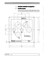
Page 15: ...4 Underfloor installation of supply lines b 3 4 Underfloor installation of supply lines 3 4 1 Installation template We recommend that you order the installation template REF 33 15 830 from Sirona for...

Page 16: ...ene inner diameter 36 5 mm 4 Water drainage DN40 HT PP ISO 8283 3 polypropylene inner diameter 36 5 mm 5 Installation pipe DN40 HT PP ISO 8283 3 polypropylene inner diameter 40 mm 6 Control cable to r...

Page 17: ...icient space is provided between the lines and the walls see Scale 1 20 The center of the hole in the floor must be 269 mm 10 5 8 from the foot of the treatment center 2 Lay the ends of the supply pip...

Page 18: ...and or blown into the treatment center Metal chips can cause malfunctions of the pneumatic components The filters become clogged with foreign materials During installation ensure that no chips or oth...

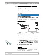
Page 19: ...cables are not crossed Laying PC connection cables HYBRID A cable duct is laid from the treatment center to the location of the PC Free length A of cables at the treatment center end Length A 600 mm...

Page 20: ...ale bar 1 20 Dentist element with travel track 4 1 1 Dimensions of the treatment room D 269 10 5 8 1450 57 1100 43 5 16 2250 88 9 16 410 16 1 8 A B 141 5 9 16 600 23 5 8 C A Recommended distances from...

Page 21: ...SINIUS TS 4 1 SINIUS dimensions scale bar 1 20 b 4 1 2 Side view 2000 78 3 4 1580 62 1 4 A A 2150 84 5 8 A 170 6 3 4 380 15 B 1226 48 1 4 930 36 5 8 1243 49 Max 957 37 5 8 Min 837 33 778 30 5 8 1480 5...

Page 22: ...3 4 801 31 1 2 1735 68 1 4 30 269 10 5 8 1930 76 A B 410 16 1 8 42 90 max 200 7 7 8 14 48 180 max 2220 87 3 8 1950 76 3 4 D C 1935 76 3 8 90 115 A Double jointed headrest Length of treatment center wi...

Page 23: ...n Requirements SINIUS SINIUS CS SINIUS TS 4 1 SINIUS dimensions scale bar 1 20 b 4 1 4 Top view with options 181 7 1 8 291 11 1 2 E D 750 29 1 2 770 30 3 8 750 29 1 2 670 26 3 8 600 23 5 8 180 7 C 85...

Page 24: ...269 10 5 8 1450 57 2250 88 9 16 410 16 1 8 A B 141 5 9 16 1360 53 1 2 D E 210 F C 600 23 5 8 A Recommended distances from cabinet or wall B Center of the floor cut out installation area C Minimum dis...

Page 25: ...ar 1 20 b 4 1 6 Side view with HELIODENT Plus 1300 51 3 16 2020 79 1 2 1170 46 660 26 C 297 11 5 8 1110 43 3 4 281 11 48 1 7 8 343 13 1 2 213 8 3 8 50 2 75 3 A B A Recommended installation height for...

Page 26: ...ment room 1250 49 1 4 1300 51 3 16 2250 88 9 16 410 16 1 8 A 269 10 5 8 B 141 5 9 16 Pos 1 Pos 2 D C A Recommended distances from cabinet or wall B Center of the floor cut out installation area C Haza...

Page 27: ...s scale bar 1 20 b 4 2 2 Side view 1226 48 1 4 930 36 5 8 1243 49 Max 800 31 1 2 Min 360 14 1 8 Max 1353 53 1 4 Min 967 38 778 30 5 8 181 7 1 8 291 11 1 2 Pos 1 Pos 2 D D 2000 78 3 4 1580 62 1 4 A A 2...

Page 28: ...9 41 11 16 max 200 7 7 8 1935 76 3 8 269 10 5 8 180 14 48 90 115 max 2180 85 3 4 1930 76 A B max 2220 87 3 8 1950 76 3 4 D C A Double jointed headrest Length of treatment center with patient height of...

Page 29: ...nstallation Requirements SINIUS SINIUS CS SINIUS TS 4 2 SINIUS CS dimensions scale bar 1 20 b 4 2 4 Top view with options 181 7 1 8 A C B 291 11 1 2 Pos 1 Pos 2 750 29 1 2 770 30 3 8 180 7 85 90 300 3...

Page 30: ...250 49 1 4 2250 88 9 16 410 16 1 8 A 269 10 5 8 B 141 5 9 16 D E 210 F C 600 23 5 8 A Recommended distances from cabinet or wall B Center of the floor cut out installation area C Minimum distance with...

Page 31: ...bar 1 20 b 4 2 6 Side view with HELIODENT Plus 1300 51 3 16 2020 79 1 2 1170 46 660 26 C 297 11 5 8 1110 43 3 4 281 11 48 1 7 8 343 13 1 2 213 8 3 8 50 2 75 3 A B A Recommended installation height fo...

Page 32: ...ons scale bar 1 20 Dentist element as swivel table 4 3 1 Dimensions of the treatment room 1250 49 1 4 1100 43 5 16 2440 96 1 16 450 17 3 4 A C 269 10 5 8 B 181 7 1 8 A Recommended distances from cabin...

Page 33: ...SINIUS CS SINIUS TS 4 3 SINIUS TS dimensions scale bar 1 20 b 4 3 2 Side view 1226 48 1 4 930 36 5 8 1243 49 Max 800 31 1 2 Min 360 14 1 8 Max 1270 50 Min 850 33 1 2 778 30 5 8 2000 78 3 4 1580 62 1 4...

Page 34: ...1059 41 11 16 max 200 7 7 8 1935 76 3 8 269 10 5 8 180 14 48 90 115 max 2180 85 3 4 1930 76 A B max 2220 87 3 8 1950 76 3 4 D C A Double jointed headrest Length of treatment center with patient heigh...

Page 35: ...l data Installation Requirements SINIUS SINIUS CS SINIUS TS 4 3 SINIUS TS dimensions scale bar 1 20 b 4 3 4 Top view with options 181 7 1 8 C 291 11 1 2 750 29 1 2 770 30 3 8 180 7 C 85 90 300 310 B A...

Page 36: ...2440 96 1 16 450 17 3 4 A D 269 10 5 8 B 181 7 1 8 1360 53 1 2 E 210 F 600 23 5 8 C A Recommended distances from cabinet or wall B Center of the floor cut out installation area C Minimum distance with...

Page 37: ...bar 1 20 b 4 3 6 Side view with HELIODENT Plus 1300 51 3 16 2020 79 1 2 1170 46 660 26 C 297 11 5 8 1110 43 3 4 281 11 48 1 7 8 343 13 1 2 213 8 3 8 50 2 75 3 A B A Recommended installation height fo...

Page 38: ...an adapter plate is available for this purpose You can use the existing drill holes for fastening Two additional drill holes are required only in the area of the water unit The treatment center is scr...

Page 39: ...not permit permanent connection of the unit e g demo operation at a trade show floor heating installation on a steel demo plate is possible The treatment center is screwed onto the steel plate using M...

Page 40: ...ents SINIUS SINIUS CS SINIUS TS 4 5 Information on planning for the practice The following file s for practice planning are available for download in the dealer area of the Sirona website under DOWNLO...

Page 41: ...kW Power consumption in Standby mode 3 W without internal mini PC Main building fuse Automatic circuit breaker type B 100 115 V AC 20 A slow burn 230 V AC 16 A slow burn Protection class Class I equi...

Page 42: ...idity 10 95 Air pressure 500 hPa 1 060 hPa Operating conditions Ambient temperature 10 C 40 C 50 F 104 F Relative humidity 30 85 no condensation Air pressure 700 hPa 1 060 hPa Installation location 30...

Page 43: ...ssistant element 126 cm x 72 cm x 75 cm SINIUS CS dentist element 136 cm x 86 cm x 65 cm SINIUS TS dentist element 154 cm x 57 cm x 80 cm SINIUS CS TS assistant element 88 cm x 35 cm x 74 cm Water uni...

Page 44: ...14 1993 concerning medical devices RoHS Directive The treatment center complies with the requirements of the RoHS Directive 2011 65 EU and AFNOR marks of the amalgam separator also for France The ama...

Page 45: ...the R TTE directive 1999 5 EC Standards EN 60950 1 EN 301489 1 EN 301489 17 EN 300328 FCC for wireless foot control The modules meet the requirements of the Federal Communications Commission Part 15...

Page 46: ...f other devices If this proves to be unavoidable the UNIT should be monitored to ensure that it is operating properly Accessories for EMC measurement Accessories for EMC measurement The EMC measuremen...

Page 47: ...rmity Electromagnetic environment guidelines RF emissions according to CISPR 11 Group 1 The UNIT uses RF energy only for its internal function Therefore its RF emissions are very low and are not likel...

Page 48: ...kV common mode voltage 1 kV differential mode 2 kV common mode voltage The quality of the line power supply should be that of a typical commercial or hospital environment Voltage dips short interrupti...

Page 49: ...performance characteristics are observed it may be necessary to take additional measures such as reorientation or repositioning of the UNIT 3 Over the frequency range 150kHz to 80 MHz field strengths...

Page 50: ...power of the communication device as shown below The recommended safety distance d in meters m can be determined for transmitters whose maximum power rating is not specified in the above table using...

Page 51: ...trol and in the base of the chair of the treatment center These modules transmit the foot control signals Wireless module in the wireless foot control and in the treatment center Foot control wireless...

Page 52: ...cklist 6 1 Installation site We recommend performing an inspection of the circumstances on location at least 4 weeks prior to installation The checklist should help you when doing this This can help e...

Page 53: ...P ISO 8283 3 or corresponding flat conduit Connections Electrical see On site installation 9 Power cable 3 x 1 5 mm Type B automatic circuit breaker 230 V AC 16 A slow blow or Type B automatic circuit...

Page 54: ...lution mini PC required in the base of the chair PC in treatment room PC system requirements IT hardware and software requirements are described in the document Installation notes and system requireme...

Page 55: ...ork should be equipped with 100 MBit Ethernet Cat 5 Cat 6 10Mbps 100Mbps Network connection for SINIUS available Network connection for external PC available IMPORTANT The use of routers between SINIU...

Page 56: ...address assignment Yes No NOTICE A static address should be assigned for the SINIUS It must not lie in the dynamic address range SINIUS _____ _____ _____ ____ Internal PC _____ _____ _____ ____ Extern...

Page 57: ......

Page 58: ...t K p a p d e OMNQ p W m d aPRSNKMONKMNKMSKMO NOKOMNQ KJk KW NNV VSS p a p d e rp W c PN aJSQSOR _ d K K p a p ii QUPR p a I p NMM I k OUOTP rp l k SP OO SSU aPRSN...

Reviews: