© 2003 - 2005 Sipura Technology, Inc
Proprietary (See Copyright Notice on Page 2)
19
Figure 4 – SPA-2000 Rear
Figure 5 – SPA-2000 Right Side
The SPA has the following interfaces for networking, power and visual status indication:
1. Two (2) RJ-11 Type Analog Telephone Jack Interfaces (Figure 5, above):
These interfaces accept standard RJ-11 telephone connectors. An Analog touchtone telephone or
fax machine may be connected to either interface. If the service supports only one incoming line, the
analog telephone or fax machine should be connected to port one (1) of the SPA. Port one (1) is the
outermost telephone port on the SPA and is labeled “Phone 1.”
The SPA-3000 has an RJ-11 interface labeled “Line” which can be used to connect the adapter to a
PSTN analog telephone circuit.
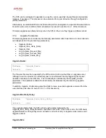
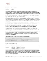
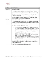
2. One LED for Unit Status (Figure 5, above):
This LED indicates status via the following behaviors:
ON – LED remains solid on
OFF – LED remains solid off
LONG (Long On) – 3.0s on, 1s off continuously
FAST – 0.1s on, 0.1s off continuously
SLOW – 0.5s on, 0.5s off continuously
VSLO (Very Slow) – 1.0s on, 1.0s off continuously
HB (Heart Beat) – 0.1s on, 0.1s off, 0.1s on, 1s off continuously
HB2 (Heart Beat 2) - 0.1s on, 0.1s off, 0.1s on, 0.1s off, 0.1s on, 1.2s off continuously
ERR0(Error 0) - 0.5s on, 0.3s off, 0.1s on, 0.1s off, 0.1s on, 2s off continuously
ERR1(Error 1) – 0.1s on, 0.1s off, 0.1s on, 0.1s off, 0.5s on, 2s off continuously
ERR2(Error 2) – 0.1s on, 0.1s off, 0.1s on, 0.1s off, 0.5s on, 0.2s off, 0.5s on, 2s off continuously
3. One Ethernet 10baseT RJ-45 Jack Interface (
Figure 3, above):
This interface accepts a standard or crossover Ethernet cable with standard RJ-45 connector. For
optimum performance, Sipura Technology recommends that a Category 5 cable or greater be used in
conjunction with the SPA.


