


16
GETTING TO KNOW YOUR WELDER….cont
Ref. No.
Description
Ref. No.
Description
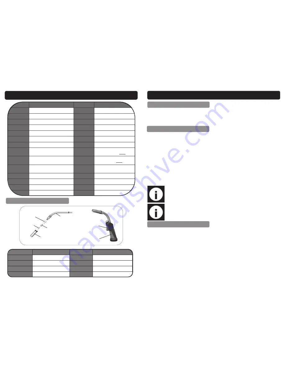
A.
Shroud
E.
Swan Neck
B.
MIG Contact Tip
F.
Torch Handle
C.
Tip Adaptor
G.
Trigger Switch
D.
Gas Diffuser
Ref.
Description
Ref.
Description
1.
4 Roll Wire Feed Unit
15.
MIG / ARC Selector
2.
Interconnecting Harness
16.
2T / 4T Trigger Mode
3.
Inverter Welding Unit
17.
Manual / Synergic Selector
4.
Welding Torch
18.
Gas Purge On / Off
5.
Large Bottle Carrier
19.
Gas Type Selector
6.
Mains Lead
20.
Welding Wire Size Selector
7.
On / Off Switch
21.
MIG Inductance Control
8.
Bottle Chain
22.
ARC Force Adj in ARC / Crater Fill
Current Adj in MIG (4T
ONLY
)
9.
Fan Cooling Inlet
23.
Welding Current Adj in ARC / Crater
Fill Volts in MIG (4T
ONLY
)
10.
Output Current Display
24.
Welding Current Adj (Wire Feed
Speed)
11.
Output Volts Display
25.
Wire Feed ‘inching’ Button
12.
Supply Volts Indicator
26.
Welding Volts Adjustment
13.
Thermal Over Load / Fault Light
27.
Wire Spool Holder
14.
Output Volts Indicator
28.
Wire Feed Motor & Assy
MIG Torch
A
G
F
F
G
A
B
C
D
E
21
OPERATING INSTRUCTIONS….cont
Clean the area to be welded, and the earthing point of all rust, paint and con-
taminants etc.
Place the earth clamp on to a cleaned area of the work piece.
PREPARATION FOR WELDING
Use the main On/Off switch on the rear of the welder to turn it on.
Select MIG symbol on the front panel.
Select MAN.
Select gas type; CO2 or MIX (Argon & CO2)
Select wire size; 0.8mm, 1.0mm or 1.2mm
Set the Weld Voltage, Wire Speed (Current Control), and the inductance by turn-
ing the appropriate controls.
Press the torch trigger and feed the wire out a little.
Cut the wire about 3mm from the MIG contact tip.
Turn the gas on .
Place a welding mask/shield over your face (not supplied).
WELDING—Manual MIG
Note: If the welder has a humming sound and a blob forms on the tip end, then you have insufficient wire
feed speed and it should be increased. If the welder has an erratic sound and the torch feels that the wire is
hitting against the work, then you have the wire feed speed to high and it should be reduced, when the wire
feed speed is correct you should get a steady crackling sound.
Note:
For future reference make a note of the voltage and wire speed set-
ting for the material that has been welded.
WELDING—Synergic MIG
Select SYN.
Select gas type; CO2 or MIX (Argon & CO2)
Select wire size; 0.8mm, 1.0mm or 1.2mm
Set the Weld Voltage, Wire Speed (Current Control), and the inductance by turn-
ing the appropriate controls.
Perform a weld test until you are happy with the welding condition selected.
There is no need to adjust the “Weld Voltage” knob again.
By turning the “Weld Current” knob the welding power and wire feed will auto-
matically adjust together. This enables the power range to be adjusted quickly
making it versatile for jobs requiring several power settings.
NOTE:- Adjustments CANNOT be made during welding.


