34
C3
C2
C1
C0
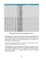
Dec
Function
0
0
0
0
0
Video standard
0 = 720p25
1 = 720p30
2 = 720p50
3 = 720p59
4 = 720p60
5 = 1080p24
6 = 1080p25
7 = 1080p29
8 = 1080p30
9 = 1080i50
10 = 1080i59
11 = 1080i60
0
0
0
1
1
User defined.
0
0
1
0
2
User defined.
0
0
1
1
3
User defined.
0
1
0
0
4
User defined.
0
1
0
1
5
User defined.
0
1
1
0
6
User defined.
0
1
1
1
7
User defined.
1
0
0
0
8
User defined.
1
0
0
1
9
User defined.
1
0
1
0
10
User defined.
1
0
1
1
11
User defined.
1
1
0
0
12
User defined.
1
1
0
1
13
User defined.
1
1
1
0
14
User defined.
1
1
1
1
15
Interface test
Table 6 aCVi Control words Transmitter > Receiver
The next three bits must be a 010 sequence (to ensure the uniqueness of
the framing byte). The next 9 bits are the data for that control function. This
is an 8-bit byte with any value between 0 and 255. The data byte is
separated into ‘nibbles’ each of 4 bits, separated by a ‘0’, again to ensure
the uniqueness of the framing byte.
The last two bits are parity bits, one for the control word and one for the
data word. The parity bits are both even parity.
The total length of the data sequence is 27 bits. Each symbol (bit) is 32 x
1/74.25MHz long = 430ns. The low bit rate ensures that the data is received
over long cable lengths even if the pre-emphasis is incorrectly set, (the
symbol length equates to a 2.23MHz data rate, which is attenuated
<2dB/100m of cable).
Summary of Contents for SM02
Page 13: ...13 Menu control The complete menu structure is shown in Figure 4 Figure 5 SM02 Menu structure ...
Page 20: ...20 Figure 7 aCVi output 30MHz sweep Pre emphasis maximum Exit Returns to the top level menus ...
Page 23: ...23 Figure 10 SMPTE Colour Bar component waveform Figure 11 SMPTE Reverse colour bars waveform ...
Page 37: ...37 ...
Page 38: ...38 ...


