33
6. aCVi Data transfer protocol
The aCVi interface allows for the bi-directional transmission of control data
between the transmitter and receiver. The data is transferred during to two
dedicated lines of the vertical blanking interval, one for transmitter to
receiver transmission, the other for receiver to transmitter.
One byte of data is sent for each line, allowing a maximum of 60 bytes to be
transferred each second, (for a 60Hz frame rate).
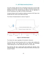
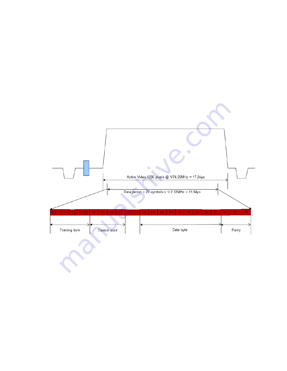
The format of the data transfer is shown in Figure 23.
Figure 23 aCVi Data format.
The format is the same regardless of the direction of transfer.
The first 8 bits are the framing byte which is a unique code signifying the
beginning of data. The receiving device must monitor the pre-defined
vertical blanking line for this framing byte which is a unique code.
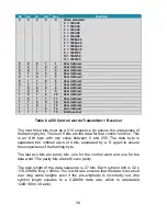
The next four bits are a control word which defines the function of the
following data byte. The control words between transmitter and receiver are
shown in Table 6.
Summary of Contents for SM02
Page 13: ...13 Menu control The complete menu structure is shown in Figure 4 Figure 5 SM02 Menu structure ...
Page 20: ...20 Figure 7 aCVi output 30MHz sweep Pre emphasis maximum Exit Returns to the top level menus ...
Page 23: ...23 Figure 10 SMPTE Colour Bar component waveform Figure 11 SMPTE Reverse colour bars waveform ...
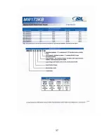
Page 37: ...37 ...
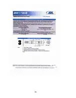
Page 38: ...38 ...


