


109
GB
109
GB
j) When the cylinders have been
fi
lled correctly and the process completed,
make sure that the cylinders and the equipment are removed from site
promptly and all isolation valves on the equipment are closed off.
k) Recovered refrigerant shall not be charged into another refrigeration
system unless it has been cleaned and checked.
• Labelling
Equipment shall be labelled stating that it has been de-commissioned and
emptied of refrigerant. The label shall be dated and signed. For appliances
containing
fl
ammable refrigerants, ensure that there are labels on the
equipment stating the equipment contains
fl
ammable refrigerant.
• Recovery
When removing refrigerant from a system, either for servicing or
decommissioning, it is recommended good practice that all refrigerants are
removed safely. When transferring refrigerant into cylinders, ensure that only
appropriate refrigerant recovery cylinders are employed. Ensure that the
correct number of cylinders for holding the total system charge are available.
All cylinders to be used are designated for the recovered refrigerant and
labelled for that refrigerant (i.e. special cylinders for the recovery of refrigerant).
Cylinders shall be complete with pressure-relief valve and associated shut-off
valves in good working order. Empty recovery cylinders are evacuated and, if
possible, cooled before recovery occurs. The recovery equipment shall be in
good working order with a set of instructions concerning the equipment that
is at hand and shall be suitable for the recovery of all appropriate refrigerants
including, when applicable,
fl
ammable refrigerants. In addition, a set of
calibrated weighing scales shall be available and in good working order. Hoses
shall be complete with leak-free disconnect couplings and in good condition.
Before using the recovery machine, check that it is in satisfactory working order,
has been properly maintained and that any associated electrical components
are sealed to prevent ignition in the event of a refrigerant release. Consult
manufacturer if in doubt.
The recovered refrigerant shall be returned to the refrigerant supplier in the
correct recovery cylinder, and the relevant waste transfer note arranged.
Do not mix refrigerants in recovery units and especially not in cylinders. If
compressors or compressor oils are to be removed, ensure that they have been
evacuated to an acceptable level to make certain that
fl
ammable refrigerant
does not remain within the lubricant. The evacuation process shall be carried
out prior to returning the compressor to the suppliers. Only electric heating to
the compressor body shall be employed to accelerate this process. When oil is
drained from a system, it shall be carried out safely.
109
Summary of Contents for SNG21-09IVi
Page 3: ...3 GR 1 2 3 4 5 6 7 service...
Page 4: ...4 GR R32 R32 GWP 675 R32 R32 R32...
Page 5: ...5 GR service 4m2 R32 1 band wifi 2400MHz 2483 5MHz 2 wifi 20dBm...
Page 6: ...6 GR q q q q q q q q q blue fins q...
Page 7: ...7 GR q q q q q q q q q...
Page 8: ...8 GR q q q q q q 3 q q q q...
Page 9: ...9 GR q q q q q q q NEC CEC q q q q q...
Page 10: ...10 GR q q q q q q q q q q m2 49 q...
Page 11: ...11 GR DB WB C DB WB C 32 23 43 26 27 24 18 15 C 43 C Temp indicator Power indicator aux...
Page 12: ...12 GR...
Page 13: ...13 GR I Feel TURBO AUTO 8 C X FAN WiFi LIGHT...
Page 14: ...14 GR q q beep q q Light 1 ON OFF 2 MODE AUTO COOL DRY FAN HEAT AUTO AUTO FAN SWING...
Page 16: ...16 GR AUTO DRY X FAN FAN 2 AUTO FAN HEAT 2 FAN 4 SWING 2...
Page 18: ...18 GR 3 5 9 WIFI WiFi WiFi 5 WiFi WiFi MODE WiFi 1 WiFi 10 Light...
Page 22: ...22 GR I FEEL c d c d LOCK MODE d MODE d C F 1 ON OFF 2 MODE 3 c d AUTO 4 FAN 5 SWING...
Page 23: ...23 GR 1 2 7 1 5V 3 8 aux AUTO...
Page 24: ...24 GR 1 2 aux...
Page 25: ...25 GR 3 45 C 4 1 2 3 4...
Page 26: ...26 GR service 5 service 1 2 3 service 1 2...
Page 27: ...27 GR 3 8...
Page 28: ...28 GR 3...
Page 29: ...29 GR AUTO AUTO 16 C 30 C...
Page 30: ...30 GR 5 8 U8 H6 H3 E1 C5 F1 F2 F0...
Page 31: ...31 GR 210 5386490...
Page 32: ...32 GR 15cm 250 cm 15cm 300cm 15cm...
Page 33: ...33 GR 50cm 30cm 30cm 50cm 200cm...
Page 34: ...34 GR 1 2 3 4 5 6 7 8 1 2 3 4 5 6 2 5 7 8...
Page 35: ...35 GR 1 2 3 4 5 1 2 3 4 5 6 7 8...
Page 36: ...36 GR 9 R32 1 2 3 4 5 9 12 10 17 21 16...
Page 37: ...37 GR 1 2 3 1 150mm 150mm 55mm 70mm 55mm 70mm...
Page 38: ...38 GR 2 3 55 70 5 10 1 2 55 70 5 10...
Page 39: ...39 GR 1 2 3 4 1 m 1 4 15 20 3 8 30 40 1 2 45 55 5 8 60 65 3 4 70 75...
Page 40: ...40 GR 2 1...
Page 41: ...41 GR 2 3 4 5 M 9K 12K N 1 3 2...
Page 42: ...42 GR 1 2 3 4 1 2 3...
Page 43: ...43 GR 4 5 1 2 3 3...
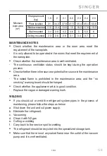
Page 44: ...44 GR 2300W 5000W 6000W 8000W 10000W 16000W 1 2 1 2 1...
Page 45: ...45 GR 2 3 4 1 m 1 4 15 20 3 8 30 40 1 2 45 55 5 8 60 65 3 4 70 75...
Page 46: ...46 GR L N M M 9K 12K 2 1 10 2 U U...
Page 47: ...47 GR O O O...
Page 48: ...48 GR 1 2 3 0 1 4 1 2 0 1MPA 5 6 2 7 Lo Hi...
Page 50: ...50 GR 1 2 3 1 2 ON OFF MODE AUTO COOL DRY FAN HEAT 16oC 1 5 7 5 8 2 3 3...
Page 54: ...54 GR 2...
Page 55: ...55 GR R32...
Page 56: ...56 GR 1 2...
Page 57: ...57 GR 3 30 40 1 4 5 6...
Page 58: ...58 GR 7 8 Ampere...
Page 59: ...59 GR...
Page 60: ...60 GR 80...
Page 61: ...61 GR...