background image

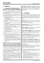
1.5.  HOW TO READ THE INSTRUCTION 

MANUAL

The Manual is split into chapters, each one dedicated 

to a specific category of information addressed to the 

personnel for whom the relevant qualifications have 

been defined.

To facilitate immediate comprehension of the text, 

terms, abbreviations and pictograms are used, the 

meanings of which can be found in Paragraph 1.6.

1.6.  TERMS, SYMBOLS  AND PICTO-

GRAMS

To highlight parts of text of significant importance 

the following symbols were adopted:

ATTENTION: Indicates the need to adopt appropri-

ate behaviours so as not to put people's health and 

safety at risk and not to cause damage to the ma-

chine or the environment.

HAZARD: Indicates situations of serious danger that 

can seriously endanger the health and safety of peo-

ple.

IMPORTANT: Indicates technical information of par-

ticular importance which should not be neglected.

The following pictogram stickers are affixed to the 

machine, depending on the version:


The product complies with the safety 

requirements provided by the applica-

ble EU directives or regulations. 


Carefully read the instructions listed in 

the manual.


Machine subjected to general danger 

(see instruction manual).


Machine used in environments with a 

high risk of electric shock.


WARNING! 

Moving mechanical parts.

(For MIG generators only)

 • capable of comprehending and interpreting the 

operator manual and the safety instructions;

 • familiar with the emergency procedures and how 

to implement them;

 • have understood the operational procedures es-

tablished by the machine's Manufacturer.

1.3.  STORAGE OF THE INSTRUCTION 

MANUAL

The Instruction Manual must be carefully stored and 

must accompany the machine each time it changes 

hands throughout its life cycle.

It should be kept in good condition by handling it 

with care, with clean hands, and not placing it on 

dirty surfaces.

Parts of the manual must not be removed, torn or 

changed.

The Manual should be kept close to the machine to 

which it refers in an environment free from humidity 

and heat.

1.4.  UPDATING THE INSTRUCTION 

MANUAL

The Manufacturer is only liable for the Instructions 

issued and validated by itself (Original Instructions); 

any translations MUST always be accompanied by 

the Original Instructions to verify the correctness of 

the translation. In any case, the Manufacturer is not 

liable for translations that have not been approved 

by the Manufacturer himself, thus if an inconsisten-

cy is detected, attention must be paid to the origi-

nal language and, if necessary, the manufacturer's 

sales office should be contacted, which will make the 

changes deemed appropriate.

The Manufacturer reserves the right to make chang-

es to the project, changes/improvements to the ma-

chine and updates to the Instruction Manual without 

previously informing Customers. However, should 

changes be made to the machine installed at the 

Customer's site, in agreement with the Manufacturer 

and involving the adaptation of one or more chap-

ters of the Instruction Manual, the Manufacturer shall 

provide the Customer with the parts of the Instruc-

tion Manual that concern the change, with the new 

global revision model. The Customer shall be respon-

sible, following the instructions that accompany the 

updated documentation, for replacing any parts that 

are no longer valid with the new ones.

5

1.995.229 EN - Rev. 1.1

NOVATIG 403 DC PULSE

Summary of Contents for NOVATIG 403 DC PULSE

Page 1: ...Original instructions in Italian Please keep for future use 1 995 229 EN Rev 1 1 INSTRUCTION MANUAL for installation use and maintenance of welding machines MODEL NOVATIG 403 DC PULSE...

Page 2: ...ARATION BY THE CUSTOMER 7 3 SAFETY 8 3 1 GENERAL SAFETY WARNINGS 8 3 2 INTENDED USE 12 3 3 CONTRAINDICATIONS FOR USE 13 3 4 HAZARDOUS AREAS 13 3 5 SAFETY DEVICES 13 3 6 SIGNS 13 3 7 RESIDUAL RISKS 14...

Page 3: ...control 26 6 5 REMOTE CONTROL CONFIGURATION 27 6 5 1 Wireless remote control Configuration 27 6 5 2 Wire foot pedal Configuration 28 6 6 START UP 29 6 7 NORMAL STOP 29 6 8 DECOMMISSIONING 29 7 MAINTE...

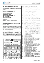
Page 4: ...PURPOSE OF THE INSTRUCTION MANUAL FOR USE AND MAINTENANCE This manual has been designed to provide the user with general knowledge of the machine and to allow it to be used safely This instruction man...

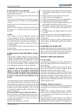
Page 5: ...TRUCTION MANUAL The Instruction Manual must be carefully stored and must accompany the machine each time it changes hands throughout its life cycle It should be kept in good condition by handling it w...

Page 6: ...t alternating current symbol Pos 15 Rated power voltage Pos 16 Maximum current in TIG welding Pos 17 Actual current in TIG welding Pos 18 Maximum current in MMA welding Pos 19 Actual current in MMA we...

Page 7: ...1 2014 35 EV 9231 EEC 9368 EEC Standards EN IEC 61000 3 12 EN IEC 61000 3 11 EN IEC 61000 3 3 2 5 INFORMATION ON TECHNICAL ASSISTANCE The machines are covered by a warranty as provided for in the gen...

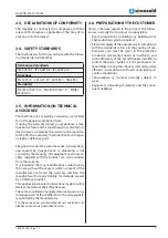
Page 8: ...ts and safeguard safety can not be modified or removed but must be adequately safeguarded The user must promptly inform the employer or his 3 SAFETY 3 1 GENERAL SAFETY WARNINGS WARNING your safety dep...

Page 9: ...rkingsonthecylinders Itisillegalanddangerous direct superior of any defects or anomalies presented on the mobile parts A Electric shock ELECTRIC SHOCK CAN BE FATAL All electric shocks are potentially...

Page 10: ...solvent vapours can be drawn into the welding atmosphere or if radiant energy can penetrate into atmospheres containing even tiny amounts of trichloroethylene and perchlo rethylene Do not lift the cy...

Page 11: ...achine must be correctly closed during the welding and cutting operations The welding ma H Moving parts can cause damage Moving parts such as the fan can cut fingers and hands and catch clothes Keep a...

Page 12: ...rty chine must never be modified in any part except for modifications planned and authorised by the manu facturer and carried out by persons authorised by the manufacturer In particular the distance o...

Page 13: ...lectrical bridges and or other means that exclude power parts of the machine 3 4 HAZARDOUS AREAS The work area pertaining to the operator which is substantially the entire perimeter of the machine is...

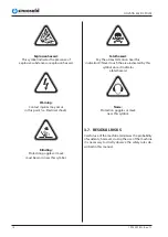
Page 14: ...minimises the probability of accidents however during the use of the machine it is necessary to strictly observe the safety rules de scribed in this manual Explosion hazard This symbol indicates the...

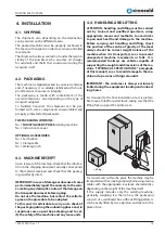
Page 15: ...the destination can be carried out by different means The packed machine must be properly anchored to the means of transport in order to avoid uncontrolled movements The shipment is always carried ou...

Page 16: ...ked during unloading from the means of transport and until it is transferred to its destination IMPORTANT The Manufacturer cannot be held liable for damage caused to persons or property due to utilisi...

Page 17: ...ift the machine by the FEEDER or genera tor handles The welder has a sturdy handle integrated in the frame for handling N B These lifting and handling devices com ply with the provisions prescribed by...

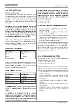
Page 18: ...of all moving parts Check that hydraulic and pneumatic connections are tight so that they do not cause dangerous leakage 4 9 CONNECTIONS Electrical connections The machine s internal connections are...

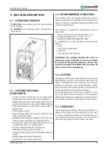
Page 19: ...general lighting to guarantee the machine has a value of 200 and 300 lux at all points of the machine 5 5 VIBRATIONS Under operating conditions that comply with the in dications for proper use the vi...

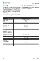
Page 20: ...g table shows the main technical specifi cations relating to the machine Parameters NOVATIG 403 DC PULSE Power supply three phases 400 V 50 60 Hz MAX current 31 5A Fuse 32A Noise emissions 70dB MAX po...

Page 21: ...iece ensuring arc starting without any contact between the tungsten and workpiece The disadvan tage of HF ignition is that the high energy electrical pulse creates significant electrical and radio sig...

Page 22: ...lding output between a high and low current output in a cyclical manner When used correctly this function has sub stantial benefits in the TIG welding process including greater weld penetration for le...

Page 23: ...materials that have higher viscosity weld pool Higher pulse duty setting will give greater heat input while lower pulse duty will have the opposite effect MMA Parameter Setting Hot start 25 Hot start...

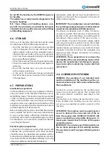
Page 24: ...N FOR MMA WELDING 6 3 1 Set up installation for MMA Welding Connection of Output Cables Two sockets are available on this welding machine For MMA welding the electrode holder is shown be connected to...

Page 25: ...er cable connected to the appropriate position not to pick the wrong voltage 11 With the corresponding input power supply terminal or socket good contact and prevent oxidation 12 With a multi meter me...

Page 26: ...red 8 After completion of welding the Power Source should be left turned ON for 2 to 3 minutes This allows the fan to run and cool the internal components 9 Switch the ON OFF Switch located on the rea...

Page 27: ...l of the power supply 2 4 seconds while at the same time turning the machine ON using the ON OFF switch on the back of the welding power supply 3 When the display on the front panel of the power suppl...

Page 28: ...operation the front panel control on the power supply is still functional but the remote control panel or foot pedal has higher priority level 7 When the remote control panel or foot pedal is idles f...

Page 29: ...time 6 6 START UP After turning on machine or line power conduct a careful visual inspection of the entire machine and make sure that no persons or material are obstruct ing its normal operation and t...

Page 30: ...tenance The operations described below must be carried out in line with the schedules indicated IMPORTANT Failure to comply with the above shall exempt the manufacturer from any liability as specified...

Page 31: ...them When reassembling the wire feeder roller after hav ing cleaned or replaced it make sure that the groove is aligned with the wire and that it corresponds to the diameter of the wire used Keep the...

Page 32: ...ck water always on E12 No gas Red lamp always on E13 Under voltage Yellow lamp thermal protection always on E14 Over voltage Yellow lamp thermal protection always on E15 Over current Yellow lamp therm...

Page 33: ...ic Equipment the user during disposal must dispose of the equipment in the appropriate authorised collection centres or re turn it still installed to the seller at the time of a new purchase IMPORTANT...

Page 34: ...e Regulations is not yet definitive please contact the distributor and or the manufacturer for information on PROFESSIONAL WEEE disposal THE SYSTEM DESCRIBED IN THE MANUAL BE LONGS TO CATEGORY DOMESTI...

Page 35: ...10 ANNEXES 10 1 WIRING DIAGRAMS 35 1 995 229 EN Rev 1 1 NOVATIG 403 DC PULSE...

Page 36: ...UCTANCE 1 26 8 221 033 HF MOUNTING BOARD 1 27 8 292 010 HULL SENSOR 1 28 8 222 019 HF INDUCTANCE 1 29 8 223 077 HF ABSORBING PCB 1 30 8 295 070 EURO SOCKET 2 31 8 295 067 12 PIN SOCKET 1 32 8 291 053...

Page 37: ...1 995 229 EN Rev 1 1 NOVATIG 403 DC PULSE 37...
Page 38: ...1 995 229 EN Rev 1 1 NOVATIG 403 DC PULSE 38...
Page 39: ...1 995 229 EN Rev 1 1 NOVATIG 403 DC PULSE 39...
Page 40: ...SINCOSALD S r l Headquarters Offices via della Fisica 26 28 20864 Agrate Brianza MB Italy Tel 39 039 641171 Fax 39 039 6057122 export sincosald it www sincosald it...

Reviews: