background image

8

ESS

 Series Installation & Start-Up 

MAN.ESS-INS, Rev. E 

SIMREX CORPORATION

Step 2—Install the Antenna

To minimize radio frequency interference, the antenna should be 
mounted at least nine inches (> 23 cm) from the connected device(s), 
sensors and other components of the system. Additional information 
on antenna selection and installation is provided in the 

DataMover 

ESS Series User’s Guide

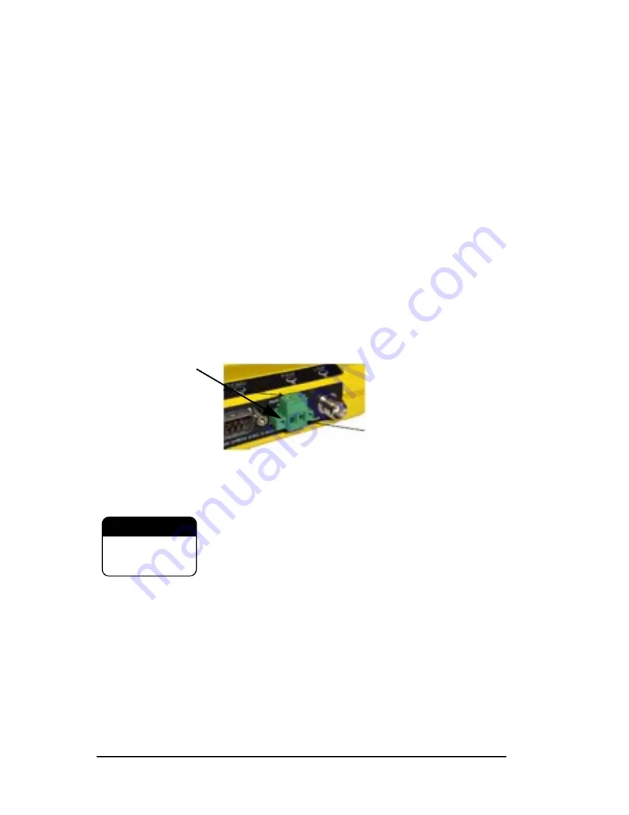
Step 3—Measure & Connect Primary Power 

The primary power at the transceiver’s power connector must be 
within 10.5–30 Vdc and be capable of continuously providing up to 
580 mA. A power connector with screw-terminals is provided with 
each unit. Strip the wire leads to 6 mm (0.25"). Be sure to observe 
proper polarity as shown in 

Figure 1

 with the positive lead (

+

) on the 

left. If the transceiver is to be powered at voltages of 28 Vdc or higher, 
please review the 

User’s Guide

 for important recommendations.

Invisible 

place 

holder

Figure 2. Power Connector

Polarity: Left +, Right –

The transceiver must be used only with negative-ground 
systems. Make sure the polarity of the power source is 
correct. 

Review complete power requirements in the 

User’s Guide, Part No. MAN.ESS-MAN.

The power supply used with the transceiver should be equipped with 
overload protection (NEC Class 2 rating), to protect against a short cir-
cuit between its output terminals and the transceiver power connector.

NOTE:

It typically takes about 30 seconds for the transceiver to power 
up, and about 20 to associate with another unit.

Step 4—Review the Transceiver’s Configuration

Two essential settings for the transceiver should be known before 
placing the unit into service. They are:

Wire Ports

Lead

Screws (2)

Binding

+ –

CAUTION

POSSIBLE

EQUIPMENT

DAMAGE

Summary of Contents for DataMover ESS Series

Page 1: ...Installation Start Up Wireless IP Ethernet Transceiver ESS II Firmware Release 1 ESS Firmware Release 6 SIMREX MAN ESS INS Rev E MAY 2006 SIMREX CORPORATION DataMover ESS Series...

Page 2: ...Refer to the Installation Reference Chart at the middle of this manual for essential installation and configuration details...

Page 3: ...8 Step 4 Review the Transceiver s Configuration 8 Step 5 Connect the Data Equipment 10 Step 6 Check for Normal Operation 11 Resetting to Factory Defaults 12 Performance Optimization 12 INSTALLATION R...

Page 4: ...ational Fire Pro tection Association NFPA publication NFPA 70 otherwise known as the National Electrical Code The transceiver has been recognized for use in these hazardous locations by two inde pende...

Page 5: ...tions outlined in this manual Failure to comply with these instructions may also void the user s authority to operate this device Environmental Information The manufacture of this equipment has requir...

Page 6: ...as Access Point unless they are first upgraded to Dual Gateway type This is accom plished with an Authorization Key purchased from the factory Each one of these individual software keys is associated...

Page 7: ...ow An accompa nying concern is the cyber security of the communication infrastruc ture and the security of the data itself The transceiver is capable of dealing with many common security issues Table...

Page 8: ...STEPS A typical product shipment consists of a transceiver a power con nector and this start up guide Below are the basic steps for installing a transceiver Should further information be needed see T...

Page 9: ...e Fasteners anchors or screws are not normally supplied Four threaded holes are located on the bottom of the radio that are suitable for connecting mounting hardware Use 6 32 x 1 4 inch 6 mm screws to...

Page 10: ...the left If the transceiver is to be powered at voltages of 28 Vdc or higher please review the User s Guide for important recommendations Invisibleplaceholder Figure 2 Power Connector Polarity Left Ri...

Page 11: ...s or 1 Mbps ESS rates are 256 kbps or 512 kbps Password Used for remote access and Menu System features NOTE The default password is admin For web access a username is also required The default userna...

Page 12: ...N port 10BaseT or one of the serial ports depending on the capability of your transceiver See Table 1 on Page 4 Use a straight through Ethernet cable to connect the LAN port to a hub and a crossover c...

Page 13: ...System PING utility At Remote Units a Look for the LINK LED to turn on and remain on This indi cates the unit has successfully associated with the network s Access Point The association process may t...

Page 14: ...lt admin you must enter a special code authorization key provided by the factory in place of the user name at the time of login Contact the factory for more information Performance Optimization After...

Page 15: ...operates only in the CHANNELS mode with select able hopping from 1 to 75 channels Usage key for Channel Configuration Menu n no Radio channel is not used y yes Radio channel is used NA not available R...

Page 16: ...ssociated with an Access Point unit by observing the LINK LED It should be on or blinking 2 View and record the Wireless Packets Dropped and Received Error rates This information will be used later Ma...

Page 17: ...ter which it will return the transceiver to normal operation The Test Mode can also be terminated manually via the menu 3 Set the transmitter RF output power to 30 dBm Main Menu Maintenance Tools Menu...

Page 18: ...g common system difficul ties using the front panel LEDs as a guide Table 6 on Page 17 pro vides guidance using the Menu System as a tool If problems persist review the SIMREX Web site s technical sup...

Page 19: ...oth ends b Verify that the appropriate type of Ethernet cable is used straight through or crossover as required Table 6 Troubleshooting with the Menu System Symptom Problem Recommended System Checks R...

Page 20: ...h local PING attempt to PING an IP unit attached to another radio d If successful with the LAN PINGs try connecting to a known unit in the WAN Wireless Retries too high Possible Radio Frequency Interf...

Page 21: ...hardware 1 5 x 6 x 4 H x W x D 3 8 x 15 2 x 10 2 cm Weight 0 9 kg 2 lb Case Cast Aluminum RADIO CHARACTERISTICS GENERAL Frequency Range 902 928 MHz Industrial Scientific Medical ISM Band Mode Freq Hop...

Page 22: ...SERVICE If return of the equipment is necessary please contact the SIMREX Technical Support Team You will be issued a Return Materials Authorization RMA number The RMA number will help expedite the re...

Page 23: ...ns should be addressed to When repairs have been completed the equipment will be returned to you by the same shipping method used to send it to the factory Please specify if you wish to make different...

Page 24: ...Installation Guide...

Page 25: ...SIMREX Corporation 5490 Broadway St Lancaster NY 14086 PH 716 206 0174 FX 716 204 0476 Web www simrex com...

Reviews: