


30 | Using radar
The radar operational modes
The radar’s operational modes are controlled from the NSO unit. The following modes
are available:
Off
The power to the radar scanner is turned off
Standby
The power to the radar scanner is on, but the radar is not
transmitting.
The radar can also be turned to standby mode by pressing the
PWR
key.
Transmit
The scanner is on and transmitting. Detected targets will be drawn on the radar PPI (Plan
Position Indicator).
If the radar is off or in standby mode you have the option to
turn the radar on or off from the radar screen:
Use the arrow keypad to select Transmit/Off and confirm
with the
Tick
key.
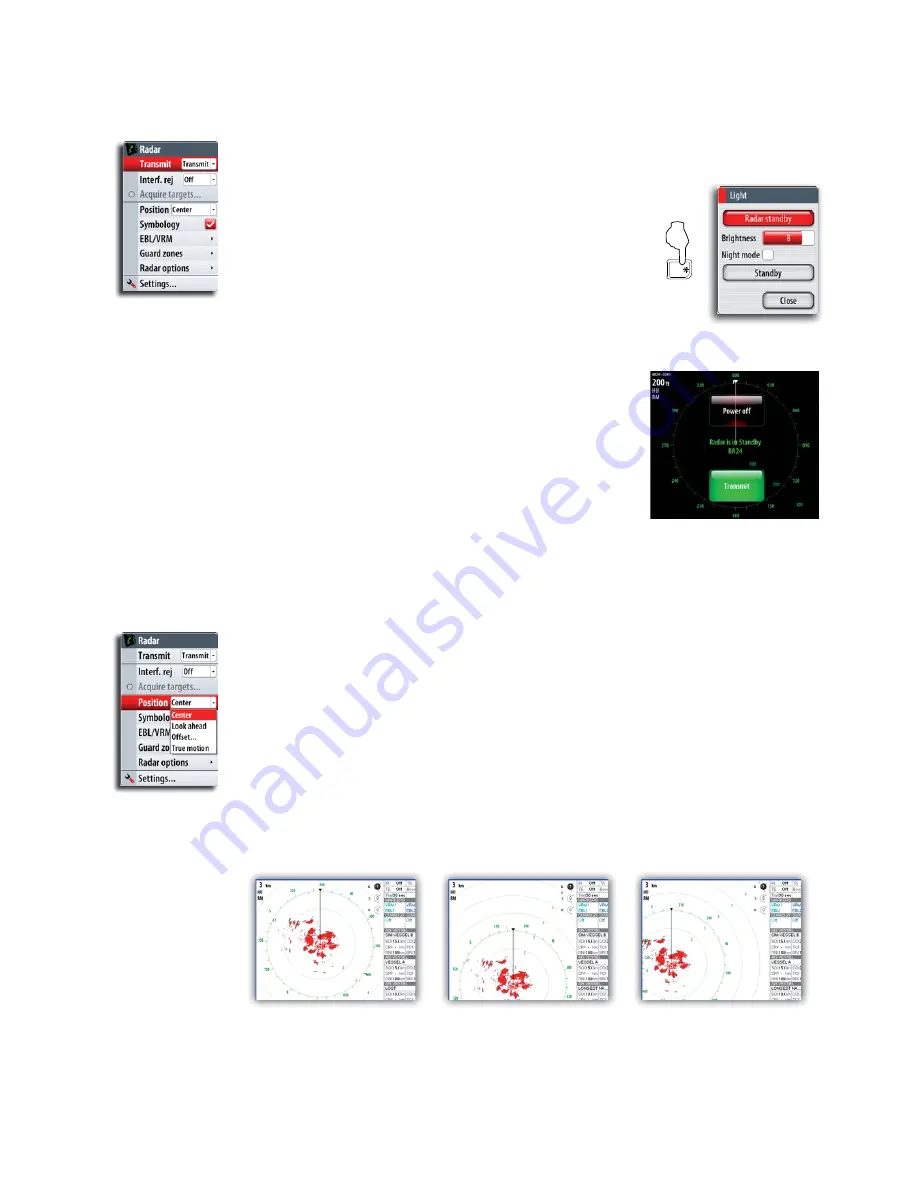
Setting up the radar image
Positioning the radar center
You can move the radar PPI center to different positions within the radar panel.
The following options are available:
Center
Default setting. The radar PPI center is centered on the radar panel.
Look Ahead
Moves the radar PPI center to the bottom of the panel to give maximum view ahead.
Offset
Allows you to move the PPI center to any location on the radar panel.
1
Select the offset option
2
Use the arrow keys to position the radar center
3
' >
Tick
key
Center
Look ahead
Custom
Setting the radar motion
You can select how your vessel symbol moves on the radar image.
The radar motion can only be changed when the radar is transmitting. If there’s no
heading data or COG, only Relative Motion mode is available.
PWR
Summary of Contents for NSO
Page 17: ...16 Simulator Blank page...
Page 43: ...42 Using radar Blank page...
Page 63: ...62 StructureScan Blank page...
Page 83: ...82 Instruments Time plots J J J J Missing Data...
Page 85: ...Blank page...
Page 89: ...88 The pages panel Blank page...
Page 103: ...102 Customizing your system RADAR MENU WIN MENU WIN...
Page 109: ...108 Maintenance MENU WIN...
Page 115: ...I Index Index 114 Weather conditions 32 96 Weather forecast 98 Weather icons 96...
Page 116: ...NSO Operation Manual English Doc no 988 10028 002 988 10028 002...


