background image

Display views

Title Bar

The ME70

Title Bar

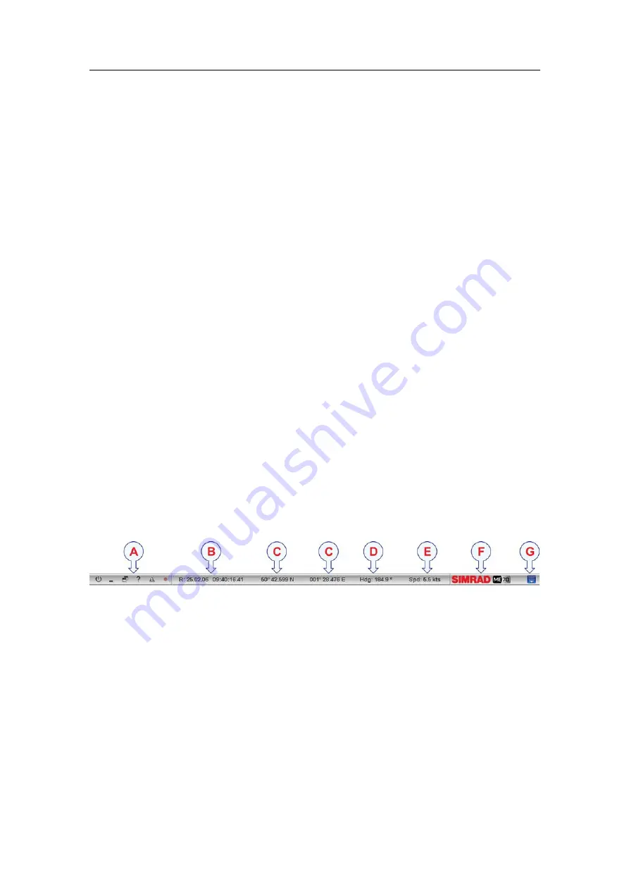
is located on the top of the display presentation, and it is stretched

from the far left to the far right side.

Topics

Purpose and description

on page 71

Logo and product name

on page 72

Operational buttons

on page 72

Menu button

on page 72

Record button

on page 73

Navigation Field

on page 73

Geographical location (latitude and longitude)

on page 73

Heading

on page 74

Speed

on page 74

Function buttons

on page 74

Purpose and description

The ME70

Title Bar

is located on the top of the display presentation, and it is stretched

from the far left to the far right side.

The purpose of the

Title Bar

is to give you fast access to key functionality and

navigational information.

It provides buttons to hide or show the menu, to start and stop data recording, to open the

Messages

dialog box, and to open the context sensitive on-line help. It also provides a

few buttons related to operating system features.

A

Function

buttons

These buttons are used to control basic system functions.

Exit

: Click this button to close down the ME70 application.

Minimize

and

Resize

: Click these buttons to adjust the size of the ME70

presentation.

Help

: Click this button to open the context sensitive on-line help.

Alarm

: Click this button to open the

Messages

dialog box. This button will flash

to indicate that a message is posted.

Record

: Click this button to start and stop recording.

B

Date and time

.

This element shows the current date and time. The prefix “R:” identifies that the
current data is replayed from a previously recorded session.

378945/B

71

Summary of Contents for ME70 - REV C

Page 1: ...Operator manual Simrad ME70 Scientific multibeam echo sounder T E C H N O L O G Y F O R S U S T A I N A B L E F I S H E R I E S www simrad com CD016018A...

Page 2: ......

Page 3: ...basic information required to operate the Simrad ME70 Multibeam scientific echo sounder For a more detailed description of the operation and functionality including menus and all parameters refer to...

Page 4: ...t does not accept liability for any errors or omissions Warning The equipment to which this manual applies must only be used for the purpose for which it was designed Improper use or maintenance may c...

Page 5: ...Power on off procedures 18 Powering up the ME70 18 Powering off the ME70 18 Restarting the ME70 19 Operating principles 20 Cursor 20 Mouse 20 Trackball 21 Presentation overview 21 Display organization...

Page 6: ...mation fields in the channel and swath views 48 Changing the size of the channel views and fields 49 Selecting which beams to see in the channel views 49 Opening a selected beam in a separate window 5...

Page 7: ...Depth field 83 Single Target Position field 84 Single target histogram field 85 Numerical field 85 Scope field 86 Echogram markers 86 MENU SYSTEM 89 About menus and buttons 90 Button types 91 Main men...

Page 8: ...Simrad ME70 6 378945 B...

Page 9: ...ll suited for those who are or wish to be expert users We assume that you are familiar with the basic acoustic principles of sound in water and that you have some experience with scientific use of son...

Page 10: ...Simrad ME70 Record of changes A 21 12 2012 First version of manual 8 378945 B...

Page 11: ...ME70 Study this chapter to familiarize yourself with the Simrad ME70 Topics Important on page 10 System description on page 11 System diagram on page 13 System units on page 14 Support information on...

Page 12: ...e to assist A list of all our dealers is provided on http www simrad com If you are unable to contact a dealer observe the support information in this chapter Related topics Support information on pag...

Page 13: ...ol Sensor input control Information display Data output and record control Replay of previously recorded data Remote control and data subscription Calibration program The Simrad ME70 scientific multib...

Page 14: ...amwidths as well as transmission modes Two systems are available to expand the utility value of the Simrad ME70 Multibeam scientific echo sounder system Bathymetric processor system for high resolutio...

Page 15: ...1 Two high quality Ethernet cables between the Transceiver Unit and the Processor Unit 2 Ethernet cable between the Processor Unit and ship s local area network 3 Ethernet cable to external data logge...

Page 16: ...perating system It provides multiple interfaces for communication with relevant pheripheral devices The Processor Unit communicates with the Ethernet switch in the Transceiver Unit by means of two hig...

Page 17: ...ransducer this allows a low impedance connection to the Transceiver Unit The array is connected to the rear side of the three transceiver racks in the Transceiver Unit using 25 cables Support informat...

Page 18: ...11 7488 Telefax 60 3 2201 3359 E mail address simrad asia simrad com Website http www simrad com Support on the Bathymetric system If you need technical support on the bathymetric units or the Seafloo...

Page 19: ...e click means that you shall place the cursor over the specified button field or function and press the left mouse or trackball button once The phrase double click means that you shall press the mouse...

Page 20: ...the circuit breakers in the Transceiver Unit are engaged c The air conditioning system in the sonar room is operational Procedure 1 Power up the colour display If required refer to the instructions pr...

Page 21: ...iver to shut down and observe the status reported by the TRU StartUp dialog box 5 Click the Exit button in the program It is located on the Title Bar in the top right corner of the display presentatio...

Page 22: ...use buttons You can then choose to click with the right button The shape and purpose of the cursor change depending on its location Move the cursor over the Title Bar at the top of the presentation an...

Page 23: ...ic version is shown as an example only A Control wheel use this to select range and gain B Trackball use this to control the cursor s location on the screen C Right mouse button use this to open conte...

Page 24: ...the name of the product ME70 It also provides several information fields and buttons These are used to hide or retrieve the menu system provide navigational information and to enable basic system fun...

Page 25: ...pened by dragging the border lines in vertical and or horizontal directions C Menu system The menu system is by default located on the right hand side of the presentation To open any of the submenus c...

Page 26: ...ext sensitive on line help Alarm Click this button to open the Messages dialog box This button will flash to indicate that a message is posted Record Click this button to start and stop recording B Da...

Page 27: ...e from left A The Operation menu controls the main operational parameters B The Display menu controls the visual aspects of the system such as parameters related to the display presentation C The Setu...

Page 28: ...numerical parameter using the buttons 1 Move the cursor to either side of the button and observe that the background colour changes a Click on the left side of the button to decrease the numerical val...

Page 29: ...ontrolled in the File Output dialog box Note Raw data files will normally become very large If you wish to record large amounts of ME70 raw data make sure that you have enough space on you hard disk U...

Page 30: ...t from the context menu that appears To create and edit beam modes see the Beam Mode Administration dialog box Related topics Beam mode procedures on page 63 Selecting beam mode for operational use on...

Page 31: ...Replay The ME70 will be paused Neither transmission nor reception takes place However you are able to play back prerecorded data files Procedure 1 Observe the Main menu It is located on the right han...

Page 32: ...open the Operation menu 2 Click Ping and select On The two icons provided by this button can also be used to enable or disable transmission The left icon rectangle is Off The right icon is On It is al...

Page 33: ...use this mode to detect and investigate background noise If the pinging has been disabled Ping set to Off the system will neither transmit nor receive 2 Active The ME70 transmissions of acoustic ener...

Page 34: ...ish to implement your chosen depth chosen depth value to all the current echograms of the same type This choice will also apply to the other methods 3 Method 3 a Click the middle of the button hold th...

Page 35: ...se or trackball to choose range value Defining the gain settings Purpose This procedure explains how to change the gain Description The Gain function controls the display gain The value controlled by...

Page 36: ...to choose gain value Saving the current user settings Purpose This procedure explains how to save the current configuration and parameter settings Procedure 1 Observe the Main menu It is located on th...

Page 37: ...puter runs a Microsoft operating system To open the help system click the Help button in any dialog box This will provide instantaneous information about the relevant dialog box with links to related...

Page 38: ...are not available for the current operation or operational mode Are there any procedures missing Are you doing an operation that we have not explained Write an e mail to simrad support simrad com and...

Page 39: ...ge 38 Choosing ME70 factory default settings on page 38 Saving the current user settings Purpose This procedure explains how to save the current configuration and parameter settings Procedure 1 Observ...

Page 40: ...on the requested saved setting in the Saved Settings list 4 Click Apply 5 Click OK to save the current settings and close the dialog box Choosing ME70 factory default settings Purpose This procedure...

Page 41: ...re called palettes Description The Palette function provides you with options for the colour scheme used on the ME70 display presentation Select the background colour and brightness to suit the ambien...

Page 42: ...0 presentations The echo colour selection is only available when you have used the No of Colours function and chosen to use 64 colours Procedure 1 Observe the Main menu It is located on the right hand...

Page 43: ...pose This procedure explains how to access the context sensitive on line help Description The ME70 is provided with an extensive context sensitive on line help system All information of the ME70 Refer...

Page 44: ...Defining the parameters for raw data recording Purpose This procedure explains how to set up the parameters for raw data recording Description The ME70 allows you to record raw data directly onto the...

Page 45: ...of the recorded files enter a maximum value for each file in the Max file size Mb field Tip Set the value to 0 Mb if you do not wish to limit the file sizes You can combine the vessel distance and max...

Page 46: ...me local area network The recording is switched on and off by means of the Record command on the Operation menu or by means of the dedicated button on the Title bar Where to place the recorded data fi...

Page 47: ...lose down the current data file being recorded and start a new This feature allows you to limit the file sizes manually 5 To play back the raw data files see Replaying raw data on page 45 Replaying ra...

Page 48: ...6 Click Replay to select this function Observe that the Replay bar opens 7 Click the start button in the Replay bar to start the playback 8 To stop the playback you have two choices a Click the stop...

Page 49: ...the separate storage device 5 Close the file manager program Presentation procedures These procedures explain how to control the presentations on the ME70 display Topics Enabling and disabling informa...

Page 50: ...le Related topics Display organization on page 69 Channel views on page 80 Display menu on page 94 Procedure 1 Place the cursor in the view 2 Right click and observe the short cut menu There are diffe...

Page 51: ...procedure explains how to choose which beams to see in the five channel views Description Five channel views are provided in the ME70 presentation There are three views next to each other in the top...

Page 52: ...y of the information You can then open the view in a separate window Related topics Display organization on page 69 Channel views on page 80 Display menu on page 94 Procedure 1 Observe the Main menu I...

Page 53: ...lour scale to use is mainly a personal preference based on ambient light conditions the nature of the echoes and your own experience Keep in mind that in the basic scale with 12 colours each discrete...

Page 54: ...red to as pinging Description The ping rate is the parameter that controls how often the echo sounder shall transmit acoustic energy a ping into the water When transmission is enabled you can choose f...

Page 55: ...lect the time in milliseconds between each ping 5 Transmitting single pings a Click Ping Mode and select Single Step b To transmit a single ping click once on the right hand icon on the Ping button Se...

Page 56: ...lick Echogram to open the Echogram dialog box The Echogram dialog box allows you to set up the parameters controlling the echogram presentation The three tabs control the horizontal lines the echogram...

Page 57: ...tal lines the echogram type with applied TVG and how sample data are converted to pixel data Tip You can also open this dialog box from the short cut menu in the Echogram view 3 On the Lines tab obser...

Page 58: ...rs you wish to see 5 Click OK to save the current settings and close the dialog box Selecting TVG gain Backscatter in the Echogram dialog box Purpose The TVG can be chosen using the Echogram dialog bo...

Page 59: ...and how sample data are converted to pixel data Tip You can also open this dialog box from the short cut menu in the Echogram view 3 On the Type tab observe the various TVG settings that can be appli...

Page 60: ...hogram type with applied TVG and how sample data are converted to pixel data Tip You can also open this dialog box from the short cut menu in the Echogram view 3 On the Lines tab observe the various l...

Page 61: ...d drag sideways 3 Method 3 a Click the middle of the button to open it b Type any depth value from the keyboard c Click Apply to all if you wish to implement your chosen depth value to all current ech...

Page 62: ...to choose range value Gain procedures These procedures explain how you can adjust the gain in the ME70 This controls how powerful the echoes are shown in the echo presentations The ME70 uses two princ...

Page 63: ...choose gain 4 Method 2 a Click the middle of the Gain button hold the mouse button depressed b Drag the cursor left or right to increase or decrease the gain 5 Method 3 a Click the middle of the Gain...

Page 64: ...ital format In order to make this work the receiver must have very large dynamic range The following TVG settings are available 1 Pr No TVG Power 2 Sv 20 log TVG Volume backscattering strength 3 Sp 40...

Page 65: ...n The currently selected beam mode is identified in the middle of the button while the four buttons two on each side identified with the numbers 1 through 4 allow you to select the top four beam modes...

Page 66: ...new beam mode Purpose This procedure explains how to create a new beam mode Related topics Beam mode procedures on page 63 Selecting beam mode for operational use on page 63 Creating a new beam mode o...

Page 67: ...uired on page 66 Exporting and importing beam mode XML files on page 66 Procedure 1 Observe the Main menu It is located on the right hand side of the ME70 presentation 2 Click the Setup icon This icon...

Page 68: ...ME70 presentation 2 Click the Setup icon This icon is located under the Main menu It is used to open the Setup menu 3 Click Beam Mode Adm to open the Beam Mode Administration dialog box The Beam Mode...

Page 69: ...typically a large capacity USB memory device or a harddisk You can also connect the ME70 computer to a network and copy the files to a server 5 Locate the beam mode description files They are all on...

Page 70: ...fields with additional information Topics Display organization on page 69 Title Bar on page 71 Replay bar on page 76 Menu system on page 77 Swath and channel views on page 78 Swath view on page 79 Ch...

Page 71: ...ifies Simrad as the manufacturer and the name of the product ME70 It also provides several information fields and buttons These are used to hide or retrieve the menu system provide navigational inform...

Page 72: ...ned by dragging the border lines in vertical and or horizontal directions C Menu system The menu system is by default located on the right hand side of the presentation To open any of the submenus cli...

Page 73: ...ality and navigational information It provides buttons to hide or show the menu to start and stop data recording to open the Messages dialog box and to open the context sensitive on line help It also...

Page 74: ...Navigation Field on page 73 Function buttons on page 74 Logo and product name The Logo and Product name is located on the right side of the Title Bar at the top of the ME70 presentation The Simrad log...

Page 75: ...e disk capacity we recommend that you save the raw data to an external storage device Related topics Saving raw data on page 44 Replaying raw data on page 45 Navigation Field The navigational informat...

Page 76: ...of the ME70 display presentation Provided that a GPS or speed log system is connected to the ME70 this field on the Title Bar will display the vessel s current speed The communication with the externa...

Page 77: ...tation Click this button to minimize the ME70 display presentation This is an operating system function To restore the presentation to its previous size click the ME70 button on the operating system s...

Page 78: ...move it sideways to adjust the replay speed D File select This button shows which file you are currently playing Click the button to open the Replay File dialog box E Progress This bar shows you the...

Page 79: ...he main operational parameters B The Display menu controls the visual aspects of the system such as parameters related to the display presentation C The Setup menu allows you to control the configurat...

Page 80: ...field on page 84 Single target histogram field on page 85 Numerical field on page 85 Scope field on page 86 Echogram markers on page 86 Related topics Display organization on page 69 Enabling and dis...

Page 81: ...re not activated the width of this section is five beams Which beams to be included in this section is defined using the Beam Selection button on the Display menu C This vertical line on the left side...

Page 82: ...ams using the Reference Beams tab in the Beam Mode dialog box the two bottom channel views will always present these reference beams Example 5 Choosing beams for the channel views If you choose beam 7...

Page 83: ...angle in degrees in the alongship X and athwarthship directions Y Tip If you right click with the cursor positioned inside the echogram field in a channel view a small short cut menu will appear to p...

Page 84: ...he field a small yellow label will appear to give you a detailed read out of certain information The Tooltip dialog box defines which information that will be shown If you press the right mouse button...

Page 85: ...strong echo signals properly Weak signals below the lower limit of the colour scale are not displayed the display background colour is used Tip If you place the cursor inside the view a small yellow l...

Page 86: ...cles all in the active layer The colours used to display this information are determined from current target strength TS value and the settings in the Colour Scale dialog box Tip If you place the curs...

Page 87: ...ed read out of certain information The Tooltip dialog box defines which information that will be shown If you press the right mouse button with the cursor position within this field a dedicated short...

Page 88: ...tings in the Echogram field The field draws a range of horizontal symmetrical colour lines The distance from the vertical centre axis and the line colour reflects the received echo scatter Tip If you...

Page 89: ...nformation it will simply push the information further down in order to make the bottom easier to see Related topics Adding horizontal markers to the echogram on page 54 Trawl line This line marker is...

Page 90: ...l line in the upper part of the echogram once every specified number of seconds d Distance This option inserts a short vertical line is drawn in the upper part of the echogram once every specified num...

Page 91: ...n and dialog box If you wish to learn more about the functionality and the parameters offered refer to the Simrad ME70 Reference manual or the context sensitive online help Topics About menus and butt...

Page 92: ...as parameters related to the display presentation C The Setup menu allows you to control the configuration of the signal processing as well as system installation and maintenance and the interfaces t...

Page 93: ...es a Click on the left side of the button to decrease the numerical value b Click on the right side of the button to increase the numerical value How to select a numerical parameter by moving the curs...

Page 94: ...log box allows you to save the current user settings parameter selections and to retrieve factory or previously saved user settings 2 Beam Mode Selection The Beam Mode Selection function allows you to...

Page 95: ...of the Operation function is to control the operational mode of the ME70 You can set it to Normal Replay or Inactive 2 Ping The purpose of the Ping function is to enable or disable the ME70 audio tra...

Page 96: ...enu Click once on the icon under the Main menu to open the Display menu Click one more time on the icon to close the menu 1 Palette The purpose of the Palette function is to choose which colour theme...

Page 97: ...ck once on the icon under the Main menu to open the Setup menu Click one more time on the icon to close the menu 1 Beam Mode Adm inistration The Beam Mode Administration dialog box allows you to creat...

Page 98: ...n current use both in Normal and Replay modes You can also enable or disable heave roll and pitch compensation 8 TRU On Off The TRU On Off dialog box permits you to start stop and restart the ME70 Tra...

Page 99: ...sate the received data for loss due to geometric spread 2 Bottom Detection The purpose of the Bottom Detection dialog box is to define the upper and lower depth limits most likely to be used during th...

Page 100: ...Histogram This Histogram dialog box is used to set parameters for the histogram displayed in the Single Target Histogram view 12 Ping Ping Filter The Ping Ping Filter removes unwanted noise and echoes...

Page 101: ...Scope short cut menu on page 103 Swath short cut menu on page 103 Tip For detailed information about every function button and dialog box refer to the ME70 Reference manual or to the context sensitive...

Page 102: ...ow The Maximize Window function allows you to enlarge the currently selected view Single Target Histogram short cut menu The Single Target Histogram short cut menu allows you to control the properties...

Page 103: ...e Echogram view in bottom related echograms The Surface Range dialog box is used to specify the vertical depth range for the Echogram view in surface related echograms You will also access these param...

Page 104: ...perties of the Numerical presentation and the current layers It opens when you right click in the Numerical presentation 1 Numerical View The Numerical View dialog box is used to select which informat...

Page 105: ...en 3 Maximize Window The Maximize Window function allows you to enlarge the currently selected view Swath short cut menu The Swath short cut menu allows you to control the properties of the Swath pres...

Page 106: ...et histogram 85 Single target position 84 Channel views descriptions 78 location 49 80 Choices Active menu 97 Colour Scale short cut menu 102 Depth short cut menu 99 Display menu 94 Echogram short cut...

Page 107: ...lette 50 colours 50 distance marker 88 field 81 ping marker 88 presentations 52 time marker 88 Echogram colours 39 Echogram line bottom line 87 Trawl line 87 Vertical ticks 87 White line 87 Echogram s...

Page 108: ...erval ping 30 52 Introduction ME70 9 L left handed Redefine mouse buttons 20 Lifting transducer 10 Lines bottom line 87 Trawl line 87 Vertical ticks 87 White line 87 Location channel views 49 80 descr...

Page 109: ...of colours 39 change palette 39 change ping rate 29 52 change presentation colours 50 change size of display fields 49 change TVG setting 56 choose echogram type 53 choose Normal operational mode 29 c...

Page 110: ...58 select 32 59 Store ME70 data 27 44 raw data 27 44 Submenus 23 70 Sunlight do NOT expose transducer 10 Surface reference 53 Swath view 79 Swath short cut menu options 103 Switch power on procedure...

Page 111: ...Index View procedures 47 swath 79 Visual presentation procedure 39 W Water temperature read 40 White line description 87 enable 57 378945 B 109...

Page 112: ...ISBN 13 2014 Kongsberg Maritime AS...

Reviews: