background image

Operation 

20222121A

 19 

2.10


Dodge in AUTO 

Dodging is useful in situations where you need to quickly take 
control of the helm to steer around an obstruction, and then 
resume the previous set heading. Dodging is activated by a quick 
double press on the 

TURN/DODGE

 button.


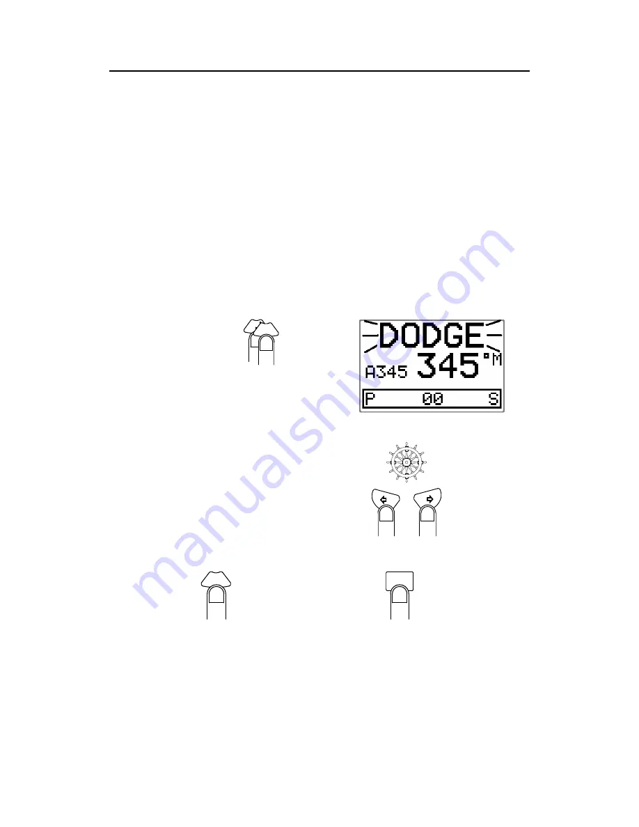
When in DODGE mode the displayed set course is the last one 
set prior to activating the dodge function. When DODGE is 
displayed, the AP16 is no longer in control of the steering, and 
you must either manually steer the boat in STBY mode or take 
control using Non Follow Up steering. The AP16 will remain in 
the DODGE mode until you exit DODGE by a second press on 
the 

TURN/DODGE

 button or select a mode. 


DO

TUR

TURN

DODGE


Quick double press on 

TURN/DODGE 

to activate Dodge mode 


Perform dodging in one of the following ways: 

1.


Manually steer the boat 
by the wheel: 


2.


Non Follow Up steering 
by pressing: 

1

or 

1


or using NFU 

steering lever

To return from Dodge mode, press one of the following: 

DODGE

TURN


Selects AUTO 
mode and 
returns to the 
last set course 


or 

AUTO


Selects AUTO 

mode with the 

current heading as 

the set course 

Note ! 

Using NFU mode while dodging will make “NFU” flash instead 
of “DODGE”. 

Summary of Contents for AP16

Page 1: ...www simrad yachting com A brand by Navico Leader in Marine Electronics Manual Simrad AP16 Autopilot for Volvo Penta IPS system English Sw 1 2 ...

Page 2: ...However an autopilot is a complex electronic system which is affected by sea conditions speed of the vessel hull shape and size and the autopilot must be operated with this in mind Please take time to read this manual to get a thorough understanding of the operation and system components and their relationship to a complete AP16 autopilot system Other documentation material that is included in thi...

Page 3: ...his work covered by the copyright hereon may be reproduced or otherwise copied without prior permission from Simrad AS The information contained in this document is subject to change without prior notice Simrad AS shall not be liable for errors contained herein or for incidental or consequential damages in connection with the furnishing performance or use of this document ...

Page 4: ...oftware record 10 2 Operation 11 2 1 Overview 11 2 2 ON OFF Standby mode 12 Flashing course knob icon 14 Alarms 14 2 3 Non Follow Up steering NFU 14 2 4 R3000X Remote Control NFU 15 2 5 JS10 Joystick NFU 15 2 6 Automatic Steering 15 Heading capture 16 2 7 Automatic control of steering parameters 17 2 8 Manual Selection of HI LO Parameters 17 2 9 U turn 18 2 10 Dodge in AUTO 19 2 11 NoDrift 20 Dodg...

Page 5: ...ive unit 35 INFO menu and Main Screen inactive unit 35 3 Installation 37 3 1 General 37 3 2 Installation checklist 37 3 3 Unpacking and handling 38 3 4 Determine system configuration 38 3 5 AP16 System Layout 39 3 6 Autopilot computer installation 39 Cable connections 39 Grounding and RFI 40 Cable strain relief 40 3 7 Control unit installation 41 Panel mounting 41 Optional bracket mounting 42 3 8 ...

Page 6: ...55 4 1 First time turn on 55 4 2 Description of Installation Settings 56 4 3 Installation Menu 57 Language selection 59 4 4 Interface Settings 59 4 5 Display units 59 4 6 Sea Trial 60 Compass calibration 61 Compass Offset 63 Wind Offset 64 Wind damping 64 Depth Offset 64 Automatic tuning 65 Transition Speed 66 Init NAV 67 NAV change limit 67 4 7 Parameters 68 Manual parameter adjust 68 Recall Auto...

Page 7: ...are programme 78 Autopilot Computer 78 Autopilot Control Unit 78 6 Trouble shooting 79 6 1 Alarms 79 7 Spare Parts List 83 8 Technical Specifications 86 8 1 AP16 Autopilot System 86 8 2 AP16 Control Unit 87 8 3 AC05 Autopilot Computer 88 8 4 RC36 Rate compass 90 8 5 R3000X Remote Control 91 8 6 JS10 Joystick 91 8 7 SimNet 92 8 8 IP protection 93 8 9 SimNet messages 94 9 Glossary 96 10 Index 99 ...

Page 8: ...y from Simrad Interfacing and steering algorithms have been developed in close cooperation with Volvo to obtain the best possible autopilot performance The way the autopilot integrates with the IPS control system is described in the IPS user manual from Volvo The autopilot system can be expanded and enhanced with a selection of options and accessories The brain in the AP16 autopilot system is the ...

Page 9: ...ystem components A basic AP16 system consists of the following units refer to Figure 1 1 AP16 Control Unit with accessories AC05 Autopilot Computer RC36 Rate compass The basic system can be expanded with fixed and hand held multiple full function control units hand held remote and steering lever Figure 1 1 AP16 Basic system Note The Volvo Autopilot Interface is the gateway between the autopilot an...

Page 10: ...RC36 Rate compass The RC36 is a fluxgate compass with integrated rate sensor It provides a dramatic improvement to the dynamic performance of both the autopilot and a stabilized radar display 1 7 Optional equipment A series of options are available for the basic AP16 system R3000X Remote Control A small handheld remote control with two push buttons for power steering or course selection port and s...

Page 11: ... 8 Software record When the system is switched on a status display shows the software versions for the control unit and the autopilot computer See page 12 Software version Description SW 1 2 00 First Volvo IPS compatible software for AP16 ...

Page 12: ...y law When using an autopilot Do not leave the helm unattended Do not place any magnetic material or equipment near heading sensor used in the autopilot system Verify at regular intervals course and position of vessel Always switch to Standby mode and reduce speed in due time to avoid hazardous situations 2 1 Overview Multifunction LCD STANDBY mode POWER on off INSTRUMENT screens setup menus AUTO ...

Page 13: ...lay Note WIND mode is not applicable hence not available in a Volvo Penta IPS configuration A group of user adjustable settings are provided in the AP16 User Setup Menu page 26 Alarms are presented in plain text to alert you of system and external data failure conditions Alarms include both audible and visual presentations The alarm listing is on page 79 2 2 ON OFF Standby mode Note At first time ...

Page 14: ...FF and during this time the alarm will sound Note In an emergency it is possible on a multistation system to turn OFF the autopilot system at any control unit by pressing the STBY button for 2 3 seconds STBY mode is the mode that is used when steering the boat at the helm Display information Standby mode Current heading 345 M Compass source Rate compass Rudder angle 00 Note Whenever you take manua...

Page 15: ...he AUTO button Alarms In the event there is an audible alarm with explaining text on the control unit refer to section 6 Trouble shooting 2 3 Non Follow Up steering NFU In Standby mode the NFU display is presented when the PORT or STBD button is pressed The rudder will move as long as the button is pressed and the rudder angle is shown on the display 1 1 Activates PORT rudder command Activates STB...

Page 16: ... the lamp is lit STBY AUTO NAV NoDrift 1 AUTO STBY STBY STBY AUTO AUTO 2 Notes 1 When NAV or NoDrift mode is selected in User Setup 2 NAV or NoDrift modes can only be entered from the Control unit 2 5 JS10 Joystick NFU The principle is similar to that of R3000X Remote Control see above The rudder will move as long as the lever is offset to Port or Starboard JS10 has no mode change feature Note Whe...

Page 17: ... the boat will automatically turn to the new heading and continue to steer straight Heading capture When in AUTO or NoDrift mode page 20 this feature allows you to automatically cancel the turn you are in by an instant press on the AUTO or NAV NoDrift button The autopilot will counteract the turn and the boat will continue straight ahead on the heading read from the compass the very moment you pre...

Page 18: ...ilot automatically changes from LO to HI parameters or opposite is determined by the Transition Speed set in the Installation Setup Menu Sea trial See diagram below Legend HI A High response parameters set automatically LO A Low response parameters set automatically HI M High response parameters set manually LO M Low response parameter set manually 26 24 22 20 18 16 14 12 10 8 6 4 2 0 LO response ...

Page 19: ...erboard situation and whenever you want to steer back on a reciprocal heading It only applies to power boats U Turn changes the current set course to be 180 degrees in the opposite direction The user must decide whether the U Turn should be made to Port or Starboard when bringing the boat on the new course U Turn is activated by a quick press on the TURN DODGE button The AP16 will continue on the ...

Page 20: ... the boat in STBY mode or take control using Non Follow Up steering The AP16 will remain in the DODGE mode until you exit DODGE by a second press on the TURN DODGE button or select a mode DO TUR TURN DO DG E Quick double press on TURN DODGE to activate Dodge mode Perform dodging in one of the following ways 1 Manually steer the boat by the wheel 2 Non Follow Up steering by pressing 1 or 1 or using...

Page 21: ...ring line unaffected by wind and current no drift The course to steer to bearing line can be changed the same way as when changing course in Auto mode Select NoDrift in the Setup menu when in STANDBY or AUTO mode Press the NAV WIND button to enter NoDrift mode The NAV WIND key is now programmed to always activate the NoDrift mode If you want the key to activate NAV mode enter the User Setup menu a...

Page 22: ...factory The navigation receiver GPS Chart Plotter must be in full operating mode with adequate signal characteristics for valid position and navigation data At least one waypoint must be entered and selected as the current Go to waypoint The navigation receiver source for the autopilot will be the one that is automatically selected in the interface set up or manually selected in the User setup men...

Page 23: ...ross track error XTE 0 012 nm to stbd Compass reading 352 M Rudder angle 00 Note For Cross Track Error the number of decimals shown depends on the output from the GPS chart plotter Three decimals give a more accurate track keeping When operating the AP16 in NAV mode to steer through a route of waypoints the AP16 will steer to the first waypoint in the route after you accept the first waypoint as t...

Page 24: ...ting the waypoint arrival circle For route navigation it is recommended to use automatic waypoint shift change at a set waypoint arrival circle The arrival circle should be adjusted according to boat speed The higher speed the wider circle The intention is to make the autopilot start the heading change in due time to make a smooth turn onto the next leg The figure below may be used to select the a...

Page 25: ...rol using the Non Follow up steering The AP16 will remain in the DODGE mode until you exit DODGE by a second press on the TURN DODGE button or until you select another mode DO TUR TURN DO DG E Quick double press on TURN DODGE to activate Dodge mode Perform dodging the same way as in AUTO mode above To return from Dodge mode press one of the following 1 DO DG E TURN Returns to NAV mode at present p...

Page 26: ...remaining control units are inactive and have no effect on mode changes or course selection A single press on any of the mode buttons on an inactive control unit will allow transfer of command and make it active 2 16 Lock function The LOCK function is a safety feature included in the AP16 system It will disable all control units except for a single user selected control unit location When the lock...

Page 27: ... 2 17 User Set up Menu In the AP16 all modes except NFU have a complemental User Set up menu You can easily access the set up menu by a quick double press on the INFO SETUP button INFO SE SETUP INFO Quick double press to access 1 1 Scroll through the menu 10 10 Change a value or setting Alternating Course Knob Icon When the PORT 10 and STBD 10 buttons are used in the User Set up menu an icon will ...

Page 28: ...pplicable mode on boats with the Volvo IPS installed Source Select Provides you with automatic or manual selection of interfaced data sources for heading Compass Navigation Position Wind Angle Wind Calculated Water speed Water temperature Distance log and Depth Wind C alculated is a common term for true wind and wind direction Auto source update Is used for automatic selection of the interfaced so...

Page 29: ...ided the data is available on SimNet If speed or depth data is provided from the Volvo IPS system to the autopilot computer the display will read IPS 2 See note on page 53 and note 3 below 3 In the event the SimNet is not powered on sources supplying data to SimNet are not on or malfunctioning or there is no SimNet installed it is possible to use any control unit in the system to select IPS as spe...

Page 30: ...the source for water temperature normally the same as the source providing depth data DisLog Select the Log source Depth Select the source for depth data Instrument Select Select the instrument page s to be available under the INFO SETUP button Step through the list of instrument pages by using the PORT 1 or STBD 1 button Select the wanted pages by filling the squares with the PORT 10 or STBD 10 b...

Page 31: ...efined that 80 85 of the boats will need no further adjustments of the steering parameters On some boats however or at particular sea conditions a fine tuning of the steering parameters may improve the performance of the autopilot The Response control allows you to make this fine tuning It can be set to seven levels Level 3 default has the values of Rudder and Counter Rudder parameters set by the ...

Page 32: ...f degrees the vessel may deviate from the set course before any command is given to the rudder The AUTO setting is recommended The MANUAL settings may be used to find the optimum combination of course keeping and low rudder activity in rough but steady sea conditions NAV WIND setting see page 27 Source select see page 27 NAV Mode The User setup for NAV mode is similar to the User setup for AUTO mo...

Page 33: ...sary if the unit is inactive The top of the screen will show the following information depending on the active mode STANDBY mode Heading AUTO mode Set course HI LO parameter Heading NAV mode HI LO parameter Cross Track Error NoDrift mode Set course HI LO parameter Heading Step through the available instrument screens by pressing the PORT or STBD button Depth Speed Depth Speed through water Speed O...

Page 34: ...int Cross Track Error Nav data Waypoint name Bearing Position Waypoint Course Over Ground Distance to waypoint Position Latitude Longitude Sea Temperature If you prefer not to have all instrument pages available in the INFO menu you may remove pages under the User setup menu See page 26 Return to last instrument screen by a simple press on the INFO SETUP button ...

Page 35: ...the mode index to tell that no course changes or other course related settings can be made unless you press a mode key The icon will time out after 3 5 seconds and be replaced by the mode index INFO menu flowchart 12 6 3 9 1 2 4 5 7 8 10 11 12 6 3 9 1 2 4 5 7 8 10 11 3 5 sec time out 3 5 sec time out Toggle 1 1 1 1 ...

Page 36: ...FO menu Note Whenever the INFO menu is active and the mode index is present on an active unit operating the PORT and STBD buttons will immediately make the main screen reappear INFO menu and Main Screen inactive unit Next INFO page Previous INFO page Last shown INFO page 1 1 You can view the INFO pages without activating the unit ...

Page 37: ...Simrad AP16 Autopilot 36 20222121A This page is intentionally left blank ...

Page 38: ...ify proper operation of the system refer to the check list below 3 2 Installation checklist 1 Determine system configuration you are installing Page 38 2 Perform the hardware installation Page 39 3 Connect SimNet devices to SimNet page 48 4 Connect NMEA2000 devices page 51 5 Connect NMEA 0183 devices via AT10 6 Perform Set up page 55 7 Perform dockside autopilot tests refer to Operating Instructio...

Page 39: ...d one 10 m 33 Robnet2 cable AC05 Autopilot computer with Interconnection cable to Volvo IPS 1 m 3 RC36 Rate Compass with 15 m 49 cable attached Three autopilot manuals use the AP16 manual Optional equipment that may have been ordered for the installation 3 4 Determine system configuration It is important to become familiar with the configuration of the system prior to beginning the installation Th...

Page 40: ... It must be mounted close to the Volvo Autopilot Interface within the length of the interconnection cable 1 m 3 See Figure 3 7 Note The autopilot computer unit is not weatherproof and should be mounted vertically in a dry environment Cable connections Use only shielded cables also for the Mains input Signal cables should be 0 5 mm2 AWG20 twisted pairs The mains supply cable should have sufficient ...

Page 41: ...ottom cover to get access to the plug in terminals Provide sufficient wire length so that the plug in terminals can be easily connected disconnected Pull out each terminal before connecting the wires Remove all strands before putting on the terminal cover Caution Do not mix the blue Robnet cable with the black Volvo IPS cable Cable strain relief Once all the cables have been run to the appropriate...

Page 42: ...o not install the control unit where moisture at the rear can be present It could cause damage by entering the breathing hole or by coming into contact with the electrical connectors Panel mounting The mounting surface must be flat and even to within 0 5 mm Drill the 4 mounting holes and make a panel cut out according to supplied template Use the supplied gasket P N 22087589 between the panel and ...

Page 43: ...The bracket can be mounted as shown on Figure 3 4 or 90 off Drill the 4 mounting holes and screw the cradle to the mounting surface Use the supplied screws to fasten the control unit to the left and right brackets Apply the front panel corners Use the two locking knobs to assemble the cradle with the left and right brackets and adjust the control head to best viewing angle Connect the Robnet2 cabl...

Page 44: ... 5 pin male connector at both ends are available in 1 5 and 10 m length For cable extension a Robnet2 T Joiner is required When installing a system try to minimize total Robnet2 cable length by connecting all Robnet2 units to the nearest available Robnet2 connector Total length of Robnet2 cable installed in a system should not exceed 50 m 165 Examples of interconnecting Robnet2 units CONTROL UNIT ...

Page 45: ...f according to IP65 when properly installed All unused Robnet2 connectors must be fitted with the plastic cap to protect them against dirt and moisture Figure 3 7 Control unit connection J1 and J2 left are Robnet2 connectors J3 and J4 are SimNet connectors Note The Volvo Autopilot Interface is the gateway between the autopilot and the IPS system The gateway kit must be ordered from Volvo under P N...

Page 46: ...played on the AP16 Control Unit the heading sensor can be mounted at a remote location The RC36 rate compass also contains a magnetic heading sensor so particular attention must be paid to the location It can be mounted on deck or bulkhead athwartship or alongship and has a 15 m 99 cable with a Robnet2 connector The heading offset feature in the AP16 will compensate for the mechanical offsets that...

Page 47: ... influences such as the engines min 2 meters engine ignition cables the IPS drive other large metal objects and particularly electric bow thrusters and anchor winches and their cables On steel hull boats it should be mounted 0 75 1 m above the wheel house on a non magnetic stand Use the supplied mounting kit and drill the holes through the centre of the slots in the sensor or the mounting brackets...

Page 48: ...e Red Green Yellow 1 4 Figure 3 10 R3000X connection 3 11 JS10 Joystick Refer to separate installation instructions supplied with the JS10 Joystick 3 12 S35 NFU Lever installation The unit is mounted to a bulkhead or panel by two screws from the front The cable is connected to the junction unit according to Figure 3 11 Interchange the Port and Stbd wires to the screw terminals if necessary to make...

Page 49: ...er equipment for data collection and exchange 1 Use SimNet 2 Use SimNet via AT10 Universal SimNet NMEA Converter 3 Connect to a NMEA2000 network via adapter drop cable part no 24005729 4 The AC05 has high speed compass heading output to Simrad and Furuno radars The different connecting diagrams on the following pages illustrate the interface possibilities of the autopilots 3 14 SimNet The SimNet c...

Page 50: ...or the new product can be connected via a drop cable SimNet power and termination The following rules should be observed when installing SimNet 1 SimNet must not be connected to a 24VDC supply 2 SimNet shall have a separate 12VDC power from the battery bus or the circuit breaker board to avoid interference 3 SimNet shall not be connected to the supply voltage terminals of the Autopilot Computer 4 ...

Page 51: ...IGHT UPPER INFO INFO LOWER SIMRAD IS12 COMBI Figure 3 12 SimNet network small system TIMER ALARM LIGHT TIMER ALARM INFO UPPER SIMRAD IS12 LOWER INFO LIGHT COMBI PAGE UPPER INFO SIMRAD IS12 INFO LOWER LIGHT COMBI LOWER INFO UPPER SIMRAD IS12 INFO DATA PW R AUTO SE TUP INFO WIND NAV STBY 10 DO DG E TURN 1 1 10 Figure 3 13 SimNet network small system with Wind transducer The wind transducer has a bui...

Page 52: ...TIMER ALARM INFO UPPER SIM RAD IS12 LOWER INFO LIGHT UPPER ALARM TIMER INFO SIMRAD IS12 INFO LOWER COMBI Figure 3 14 SimNet network medium system Notes 1 Maximum total length of SimNet cable is 40 m 130 ft excluding the 30 m 99 ft of masthead cable 2 The wind transducer has a built in terminator 3 If there is no wind transducer connected a SimNet terminator must be connected instead ...

Page 53: ...Simrad AP16 Autopilot 52 20222121A Figure 3 15 Robnet2 and SimNet network The wind transducer has a built in terminator ...

Page 54: ...is not necessary to connect all autopilot control units to SimNet for data sharing However if you want to have full redundancy and SimNet control e g select sources you have to connect the actual unit to SimNet 3 AT15 is a NMEA0183 SimNet converter for the IS15 Instrument system IS15 makes no load on SimNet 4 AT44 is a SimNet interface that is supplied with CX44 and CX54 products ...

Page 55: ...and operation of the IS15 instruments refer to separate manuals For interfacing the IS15 you need the dedicated AT15 Active Tee as an interface item pages 53 84 3 17 External Alarm The external alarm circuit has an open collector output for an external alarm relay The operating voltage for the circuit is an internal AC05 voltage Max load on the alarm voltage is 125 mA TB1 AUTOPILOT COMPUTER TB2 NF...

Page 56: ...postpone the automatic interface by going directly to the Installation Dockside setup Any time the STBY button is pressed the interface prompt will reappear until the automatic interface has been performed 2 Be aware that you will have no compass reading before the automatic interface is completed Continue by pressing the STBD 1 button to start the automatic interface set up The autopilot will sea...

Page 57: ... performed during sea trial Parameters Permits viewing and changing of basic steering parameters See also response control page 30 Service System data SimNet setup Master reset of memories Each group is designed to focus on specific functions and enable quick access when changes need to be made Some important points regarding the installation settings When the AP16 is delivered new from the factor...

Page 58: ... a pictorial view of the Installation Menu Navigate through the Installation Menu as follows Step through the functional categories by pressing the STBD 1 or PORT 1 button Access a category by pressing the STBD 10 button Step through the category items by pressing the STBD 1 or PORT 1 button Change the selected item by pressing the STBD 10 or PORT 10 button Exit the Installation Menu by pressing S...

Page 59: ...H OFFSET AUTOMATIC TUNING TRANSITION SPEED INIT NAV NAV CHANGE LIMIT TURN CCW CONFIRMED SYSTEM DATA STEERING COMPASS RUDDER INPUT VOLTAGE RADAR SIMNET DATA XTE BWW BPW POS LAT POS LON COG SOG WIND SPEED DEPTH SYSTEM DATA SIMNET DATA SIMNET SETUP Master reset DISPLAY UNITS WIND SPEED WATER TEMP DEPTH DISPLAY UNITS SIMNET SETUP SIMNET SOURCE SELECT BACKLIGHT INSTANCE NUMBER SIMNET GTWAY GLOBAL SIMNE...

Page 60: ...the STBD 1 button or leave the menu by pressing the STBY button 4 4 Interface Settings Sets the format of the clock data output for radars connected to the Autopilot Computer Step to the Interface part of the Installation Menu Press the STBD 10 button to access the Interface Setup items Use the PORT 10 or STBD 10 buttons to select the connected type of radar 4 5 Display units Select Display units ...

Page 61: ...be performed in open waters at a safe distance from other traffic The seatrial settings are Compass calibration To automatically compensate for onboard magnetic interference Compass Offset To compensate for a fixed offset A error in the final compass heading readout Wind Offset To compensate for a fixed mechanical offset of the Wind vane if installed Wind Damping To avoid flickering on the wind di...

Page 62: ...ass that comes with the autopilot as standard will store the calibration and off set data in its own memory 2 Calibration is made on the compass that is active for the autopilot The active compass is the one that is displayed on the compass calibration screen RATE 0 Rate compass Before you start the compass calibration make sure you have enough open water around you to make a full turn with the bo...

Page 63: ...llation of the compass page 45 During the calibration the compass will measure the magnitude and direction of the local magnetic field from where the compass is mounted The magnitude is given in of the magnitude of the earth s magnetic field If the local magnetic field is stronger than the earth s magnetic field the local field is reading more than 100 the compass calibration will fail If the loca...

Page 64: ... if a fixed offset remains after the calibration procedure has been completed The value of compass offset is specific to the heading sensor that is selected at the time the offset is entered This means that you can have individual offsets for each compass installed Select the amount of correction by pressing the STBD 10 or PORT 10 buttons to offset the heading to agree with the known accurate head...

Page 65: ... of the apparent wind angle is made by the Advanced Wind Filter AWF in the Autopilot Computer The inputs to the AWF are heading boat speed apparent wind angle and wind speed Verify that these inputs are available in User Setup Source Select page 27 The boat speed input to the AWF is Speed Over Ground SOG or speed through water If none of these are available the AWF will use a boat speed that is 1 ...

Page 66: ...h a number of S turns Automatic tuning is an optional procedure that is not required for the AP16 to function The AP16 is preset with steering parameters that should steer most boats in the 30 80 foot range It is however recommended to perform an automatic tuning as part of the sea trial Recommended speed during Automatic tuning varies with the type of boat but should not exceed 10 knots 6 8 knots...

Page 67: ...within the Parameters menu item See also Recall Autotune on page 70 Proceed to the next menu item by pressing the STBD 1 button or return to Standby mode by pressing the STBY button Transition Speed The transition speed is the speed where the AP16 will automatically change the steering parameter set from HI to LO parameters or vice versa page 17 The default setting of transition speed is 5 kts It ...

Page 68: ...e NAV mode at the first leg The approach angle is dependant adaptive on the distance XTE from the track line and the boat speed Select firm or soft approach to the track line using the STBD 10 or PORT 10 button Range Soft Firm Default Soft NAV change limit In NAV mode when the required course change at the approaching waypoint is more than the set limit you are prompted to verify that the upcoming...

Page 69: ...the menu items by pressing the STBD 1 or PORT 1 buttons Adjust the value by using the STBD 10 or PORT 10 buttons Manual parameter adjust Displayed parameter Default Automatic tuning Manual Use STBD 10 and PORT 10 buttons to adjust value LOw Decrease Press 10 Increase Press 10 Rudder LO 0 20 Cont Rudder LO 1 00 Autotrim LO 40 sec 1 1 HIgh Rudder HI 0 30 Cont Rudder HI 1 40 Use PORT 1 and STBD 1 but...

Page 70: ... the parameter that counteracts the effect of the boats turn rate and inertia For a short time period it is superimposed on the proportional rudder response as provided by the heading error It may sometimes appear as if it tends to make the rudder move to the wrong side counter rudder The best way of checking the value of the Counter Rudder setting is when making turns The figures illustrate the e...

Page 71: ...D 1 button to proceed to the Service menu or press STBY to return to normal AP16 operation 4 8 Service Menu The Service menu includes System data and SimNet data which are test functions to analyze data processed by the AP16 The menu can be useful when testing or trouble shooting the system Select STANDBY mode Press and hold the INFO SETUP button for 5 seconds to enter the Installation Menu Press ...

Page 72: ...minals To exit the menu press any mode key STBY AUTO or NAV SimNet Data Screen Select STANDBY mode Press en hold the NAV WIND button for 5 seconds to enter the Installation Menu Press the STBD 1 button to select SERVICE Confirm by pressing the STBD 10 button Select the screen by pressing the STBD 1 button and confirm by pressing the STBD 10 button The menu provides you with status information abou...

Page 73: ...K Valid data found INV Message with invalid information FRM Message has format failure such as a Incorrect check sum b Wrong contents in datafield s If data are missing or invalid perform the following Open the source select page in the User Setup menu and check that data are available Check the navigator setup and make sure it is transmitting appropriate data Note The WIND reading is the apparent...

Page 74: ...red to other products in the Simrad Group no synchronization Backlight Illumination Set backlight to synchronize with one of the illumination banks 1 3 available on the SimNet or to STAND ALONE for individual control of the autopilot illumination Instance number An item to identify units by a number when the autopilot is connected to a NMEA2000 Network On SimNet units the Instance number is added ...

Page 75: ...e PORT 10 button The display will then read Master Reset confirmed Unless you have made a Master Reset exit the Installation Menu by pressing STBY to return to normal AP16 operation In the event a Master Reset has been made refer to chapter 0 Final sea trial After having completed all settings in the Installation Menu take the boat out and perform a final sea trial in open waters at a safe distanc...

Page 76: ...n briefly what takes place in the different modes Regaining manual control from any mode Point out in what modes the helm is engaged by the autopilot and vice versa see page 13 Taking command at an inactive station if applicable Using the lock mode how to lock unlock and how to shut the system down from a locked control unit if applicable Use of the Non Follow up steering mode Use of a remote Non ...

Page 77: ...Simrad AP16 Autopilot 76 20222121A Locating the Mains circuit breaker and the separate SimNet circuit breaker if provided ...

Page 78: ...onnectors are fitted with a protection cap It is advisable at the start of each season to check all connections to the control unit head If the Control unit is not removed from the boat it should be covered with the white protection cover 5 2 Autopilot Computer No special maintenance is required It is advisable however at the start of each season to make a visual inspection of the internal and che...

Page 79: ...ctions are included Autopilot Computer Remove the bottom cover to get access to the software download connector Figure 5 1 Part of AC05 PCB Autopilot Control Unit Figure 5 2 Part of AP16 PCB Remove the cables and unscrew the screws that secure the back cover Apply a firm pull with your fingers to pull the back cover loose from the connector pins Then you have access to the software download connec...

Page 80: ...tified Refer to the table below for hints and try to solve the problem yourself You may also consult your nearest Simrad dealer for assistance if required Perform any repair action in the listed sequence Note in a display indicates that data is missing 6 1 Alarms Display readout Probable fault Recommended action System failure Alarms The boat is off course Boats heading is outside fixed off course...

Page 81: ...o data from selected compass 1 If more that one compass is connected to the system refer to the User Setup2 Source select menu to select a different compass 2 Make a source update if no compass is available 3 Check connections 4 Replace compass PCB Note Do not cut cables There are screw terminals inside No connection with IPS system Data missing or erratic Check connections to Volvo Autopilot Inte...

Page 82: ...n If the alarm is repeated replace Autopilot Computer PCB Com failure with ACXX Faulty Autopilot Computer or poor Robnet2 cable connections from the same 1 Check Robnet2 connectors and cable 2 Replace Autopilot Computer PCB Low supply voltage Supply voltage less than 10 8 Volts 1 Verify in the System Data Menu 2 Switch autopilot off charge batteries 3 Check repair battery charger High supply volta...

Page 83: ...Simrad AP16 Autopilot 82 20222121A This page is intentionally left blank ...

Page 84: ...or left and right bracket 44163160 Cradle locking washer 22087514 AP16 Sub Ass y incl board and front ass y 22087498 AP16 Back plate Ass y 22087373 AP16 Board Ass y 22091854 AP16 Protection Cover 22087662 AP16 Software AC05 Autopilot Computer 22089007 AC05 Autopilot Computer 44134948 AC05 Installation Accessories 22089023 AC05 PCB Ass y 22089262 AC05 SimNet Robnet2 terminal 44134922 AC05 Connector...

Page 85: ... with two plugs 24005662 Robnet2 T Joiner SimNet cables and accessories 24005829 SimNet cable 0 3 m 1 24005837 SimNet cable 2 m 6 6 24005845 SimNet cable 5 m 16 6 24005852 SimNet cable 10 m 33 24005860 SimNet T Joiner 24005878 SimNet cable gland 24005886 SimNet protection plug 24005894 SimNet termination plug 24005902 SimNet power w termination 2 m 6 6 24005910 SimNet power w o termination 2 m 6 6...

Page 86: ...Spare parts list 20222121A 85 ...

Page 87: ...dder Drive Volvo Penta IPS Parameter selection Automatic with manual override Sea state control Adaptive sea state filter or manual Language selection English Norwegian French Spanish German Italian Dutch Swedish Electronic Interface Navigation interface Standard NMEA 0183 via AT10 Compass heading output Simrad and Furuno radar display clock data NMEA2000 interface Via SimNet port and SimNet NMEA2...

Page 88: ...RMC GGA RMC RMB BWC SimNet LOG SEA TEMPERATURE VLW MTW SimNet Note Alternative messages are separated by slashes 8 2 AP16 Control Unit Dimensions See Figure 8 1 Weight 0 5 kg 1 1 lbs Power consumption 3 W Display Type Backlit LCD matrix display Resolution 160 x 128 pixels Colour Black Illumination Adjustable in 10 steps Environmental Protection IP56 from front IP43 from back Safe distance to compa...

Page 89: ...Mounting bracket is optional equipment 8 3 AC05 Autopilot Computer Dimensions See Figure 8 2 Weight 1 1 kg 2 4 lbs Supply voltage 10 8 31 2V DC Reverse voltage protection Yes Environmental Protection IP22 Safe distance to compass 1 0 m 3 ft Power consumption 5 Watt electronics ...

Page 90: ...emperature range Operation 0 to 55 C 32 to 130 F Storage 30 to 80 C 22 to 176 F Mounting Bulkhead mount Material Epoxy coated silumin and ABS Number of control units 7 Input for NFU control Yes Radar clock data interface Yes Figure 8 2 AC05 Autopilot Computer Dimensions ...

Page 91: ...d by control head Gain compensation Automatically adjusted continuously Rate sensor stabilized heading output Accuracy 1 25 rms Repeatability 0 2 rms Roll Pitch 35 degrees Cable supplied 15 m TP shielded Robnet2 cable Temperature range Operation 0 to 55 C 32 to 130 F Storage 30 to 70 C 22 to 158 F Environmental Protection IP56 Mounting Deck or bulkhead Material White ABS Figure 8 3 RFC35 Fluxgate ...

Page 92: ...ns 8 6 JS10 Joystick Figure 8 5 JS10 Joystick Dimensions Dimensions See Figure 8 5 Weight 0 5 kg 1 1 lbs Environmental Protection Joystick IP66 Terminals IP20 Safe distance to compass 0 15 m 0 5 ft Shock resistance according to MIL 202 B method 202 A 1 2 sinusoid 11 ms No damage or disassembling at 100 g Vibration resistance according to IEC 68 2 6 16 g with frequency range from 40 to 500 Hz and m...

Page 93: ...le length 120 m 400 Bit rate of the bus 250 Kbit second Maximum DC current through a single SimNet plug 5A SimNet power supply 12VDC Maximum drop cable length 6 m 20 Maximum total length of all drop cables accumulated 60 m 200 Environmental protection Cable and plug connector system IP66 Temperature 70 C 158 F ...

Page 94: ...t solid objects up to 50 mm eg accidental touch by hands 1 Protected against vertically falling drops of water eg condensation 2 Protection against solid objects up to 12 mm eg fingers 2 Protected against direct sprays of water up to 15 from the vertical 3 Protection against solid objects over 2 5 mm tools wires 3 Protected against sprays to 60 from the vertical 4 Protection against solid objects ...

Page 95: ...stance Log Data Log distance and trip 1 1 Temperature Data Water temperature 1 Position Data Present position Lat Lon 2 1 COG 2 1 Magnetic variation 1 SOG 3 2 1 Navigation Data To wp position To wp ident Bearing wp wp Bearing pos wp Distance pos wp XTE Waypoint closure velocity Steering Data Heading steering cmd T M APXX Gateway x x x x x x x x x Additional PGNs supported Simrad Propriatory 61184 ...

Page 96: ... d d x d d d x d d d x d d d x d d d x d d d x In INFO views Depth Offset is displayed if x offset is present d d d x d x d d d x d d d x d d d x x d d d x 1 x 1 d d d x 1 d d d x 1 d d d x 1 d d d x 1 d d d x 1 d d d x x x x x x Only transmitted if NMEA183 RC36 RFC35 is source Indata use AP16 AP25 AP26 Out Gateway ...

Page 97: ...aypoint Bearing angle of the line between the TO and the FROM waypoint calculated at the FROM waypoint for any two arbitrary waypoints COG Course Over Ground The actual direction of progress of a vessel between two points with respect to the surface of the earth The vessel s heading may differ from the course over ground due to the effects of wind tide currents GPS Global Positioning System This s...

Page 98: ...oduct ID A number suffix acronym or term that can identify a product Product name The name of a Simrad product known from sales and other literature Route A stored sequence of waypoints These waypoints will be listed in the order in which you desire to follow them SimNet Source Any product or device directly connected to SimNet or NMEA2000 or interfaced to SimNet via NMEA0183 or Robnet2 Simrad Gro...

Page 99: ...cated on the surface of the earth Normally this point will be identified by Lat Lon coordinates although in some systems it may be shown by T D s XTE Cross Track Error Used to identify a vessels position relative to a straight line drawn between two waypoints The amount the vessel is off to the left or to the right of this line is known as the track It is normally displayed in thousands of a nauti...

Page 100: ...nt panel 12 installation 41 maintenance 77 specifications 87 counter rudder 30 65 setting 69 Course knob icon 26 D depth offset 65 depth offset 64 depth source 28 display units 59 dodging 19 dodging in Nav mode 24 F fluxgate compass installation 45 G grounding 40 I illumination See backlight Init NAV 67 instrument installation 54 screen 32 selection 33 instrument select 29 interface setting 59 int...

Page 101: ... S seastate filter 31 seatrial final 74 service menu 70 SimNet 7 28 45 48 backlight 73 gateway 73 number 73 reset 73 setup 73 specifications 92 Simrad group 73 software program exchange 78 software setup 55 source manually update 28 source select 27 source update 27 specifications 86 steering lever installation 47 system basic 8 components 8 specifications 86 with options 39 system data 71 T trans...

Page 102: ...AP16 manual for Volvo Penta IPS system EN Doc no 20222121 Rev A ...

Reviews: