background image

Atlas  | Operation and Installation Manual 


 16


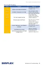
VII-D. Trouble Shooting 

Error 

Problem 

Solution 

Intake 
Temp. 

Failure 


Intake screen blocked by debris 


Ambient temperature too high


Clear intake screen, located 
on bottom of unit. 
 
Move load bank to cooler 
location or wait to conduct 
test on cooler day, if possible. 

Exhausts 

Temp. 

Failure 


Fan has stopped running 


Exhaust space insufficient 

The unit needs to be 
serviced. Please call the 
Simplex service department 
at 800-637-8603 ext. 4. 
 
Move the unit to an area that 
allows for proper air 

circulation. See “Load Bank 
Placement” on page 8 for 

more information. 

Fan failure 

Fan not blowing air into element 

chamber 


Fan blades not turning 

Clear intake screen, located 
on bottom of unit. 
 
Make sure nothing has 
jammed the fan blades. 

Over 

Voltage 

Load bank connected to too-high 

voltage source 

Connect load bank to 
appropriate voltage source. 


Maintenance/Troubleshooting - 

Summary of Contents for Atlas

Page 1: ...Atlas Operation and Installation Manual 1 Operation and Installation Manual ...

Page 2: ...d Installation Manual 2 Last Revision Date December 18 2018 For the most up to date information for this product and others please contact Simplex Inc at 800 637 8603 or visit us on the web at http www simplexdirect com ...

Page 3: ...nstallation 9 IV A Load Bank Placement 9 IV B Wiring the Load Bank 9 V Operating Instructions 11 V A Conducting a Test 11 V B Metering Line Trends Screen 11 V C Shutdown 12 V D Maintenance Mode 12 V E Diagnostics Screen 12 VI Alarms and Warnings 13 VI A Sensors 13 VI B Alarms 13 VI C Warnings 14 VII Maintenance Troubleshooting 15 VII A General Maintenance 15 VII B Each Operation 15 VII C Trouble S...

Page 4: ...operated by personnel properly trained and experienced in its use An operator s manual is supplied with each load bank and available online at www simplexdirect com The operator must be familiar with its contents and have access to it during operation High Voltage Turn off and disconnect power source before opening this equipment High Temperature Allow hardware to cool before servicing or opening ...

Page 5: ...ess adequate protection is provided Routinely inspect all components and electrical connections for tightness and integrity Repair any damaged or degraded components and wiring without delay If technical assistance service or parts are needed please call 800 637 8603 24 Hours All hardware covered by this manual have dangerous electrical voltages and can cause fatal electrical shock Avoid contact w...

Page 6: ...t aid and seek immediate medical attention Never wear jewelry when working on this equipment Jewelry can conduct electricity resulting in electric shock or may get caught in moving components causing injury Keep a fire extinguisher near the hardware at all times Do NOT use any carbon tetra chloride type extinguisher Its fumes are toxic and the liquid can deteriorate wiring insulation Keep the exti...

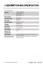
Page 7: ...pe Resistive Cooling System Airflow 27 700 CFM Motor 10 HP Voltages 240 480V 3 ph Frequency 50 60Hz standard Connection 3 wire plus ground Time Rating Continuous Ambient Air Temperature 120 F Fault Rating Fuses are rated 200KAIC The load bank has a 5KAIC short circuit current rating Fan Control Power Provided by either internal transformer or 230 460V 3 ph 60Hz external power Description and Speci...

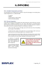
Page 8: ...k is relocated 1 If the crate shows any signs of damage examine the load bank in the corresponding areas for signs of initial problems 2 Check the entire outside of the cabinet for any visual damage which could cause internal electrical or mechanical problems due to reduced clearance 3 Inspect all relays and control modules Make sure all components are secure in their bases and safety bails are in...

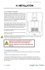
Page 9: ...ld be placed in a secure area accessible by trained personnel only Because the unit generates a lot of heat never operate near sprinkler systems Operating the load bank in a confined space will recycle hot exhaust air through the cooling system which can cause severe damage The load bank may compete with nearby generators for cooling air IV B Wiring the Load Bank 1 Confirm the test source is prope...

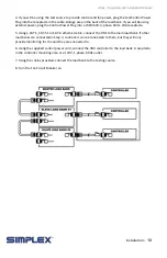
Page 10: ...eptacle 5 Using a CAT 5 CAT 5E or CAT 6 ethernet cable connect the HMI to the main load bank If other load banks are connected in Step 3 controllers can be connected to them but they will only provide monitoring for the unit they are connected to 6 Using the supplied control power cord connect the HMI controller to the load bank s receptacle in the controller mounting area or a 120V 1 phase 60Hz o...

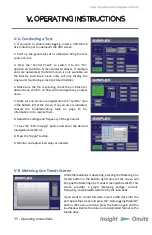
Page 11: ...of the screen If any errors are indicated consult the troubleshooting table on page 16 for information on to resolve them 6 Adjust the voltage and frequency of the generator 7 Press the KW to Apply button and enter the desired load pictured bottom 8 Press the Apply button 9 Monitor and adjust load steps as needed V B Metering Line Trends Screen While the load bank is operating pressing the Meterin...

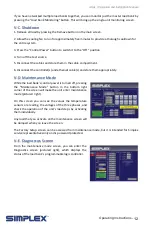
Page 12: ...propriately V D Maintenance Mode While the load bank s control power is turned off pressing the Maintenance Mode button in the bottom right corner of the screen will make the unit enter maintenance mode pictured right On this screen you can see the values the temperature sensors are reading the voltages of the three phases and check the operation of the unit s load steps by activating them individ...

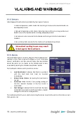
Page 13: ... red Load Bank Failure notification and the unit will dump the load Details about the alarm can be found on the Maintenance screen accessible by pressing the Maintenance Mode button The load bank s HMI can alert you to four alarms Load Bank Failure Indicates that there is a problem with the load bank that must be resolved immediately Exhaust Temp Failure Air leaving the load bank is too hot Fan Fa...

Page 14: ...l 14 VI C Warnings The load bank features one warning Intake Temp Failure This warning will not disable the unit and dump the load as with the alarms but the issue should be investigated and resolved as soon as possible Alarms and Warnings ...

Page 15: ...tors To check the fuses or load resistors operate the load bank from a balanced 3 phase source and check the three line currents on the metering screen The three current readings should be essentially the same If a sizable difference is noted one or more load fuses or load resistors may have malfunctioned VII C Trouble Shooting Any of the alarms detailed on page 13 will result in the load bank ent...

Page 16: ...ng Exhaust space insufficient The unit needs to be serviced Please call the Simplex service department at 800 637 8603 ext 4 Move the unit to an area that allows for proper air circulation See Load Bank Placement on page 8 for more information Fan failure Fan not blowing air into element chamber Fan blades not turning Clear intake screen located on bottom of unit Make sure nothing has jammed the f...

Page 17: ... parts supplied by buyer for inclusion in finished equipment are not covered by this warranty g components or assemblies specified by buyer with no substitution permissible that are not normally used by SIMPLEX SIMPLEX reserves the right to reject warranty claims of any kind against assembled equipment parts or material for which SIMPLEX has not received payment in full Should buyer at his own ris...

Page 18: ...ion Manual 18 for all your Load Bank and Fuel Supply needs 800 637 8603 www simplexdirect com This manual and all of its contents Copyright 2019 Simplex Inc All Rights Reserved Simplex Inc 5300 Rising Moon Road Springfield IL 62711 ...

Reviews: