background image


13 


Tips for applying polish 

● 

Apply polish with sweeping straight 
line strokes, either side-to-side or 
back-to-front  (see Fig. 7) 

● 

Use a thin even coat. 

● 

Do not use excessive pressure against 
the work surface. The random orbit 
action works best with little pressure. 

● 

Each time you add polish to the foam 
pad, use less polish to avoid saturating 
the pad. 

● 

Follow specific recommendations of 
the polish manufacturer. 


REMOVE POLISH 

 
1.  Allow polish to dry to a haze. 


2. 

Remove the 4” foam pad and install 
the 6” buffing pad (see Fig. 8). 

NOTES:


a) Make sure the foam pad is centred 
on the mounting plate. 
b) You can also use the 4” foam pad to 
remove polish. If you used the 4” pad 
to apply polish, it must first be 
thoroughly cleaned and dried. See 
Maintenance section of this manual for 
pad cleaning instructions. 


Tips for removing polish 

● 

Let the tool do the work. Do not apply 
excessive pressure when removing 
polish. 

● 

Move the polisher in a figure 8 pattern 
over the surface you are polishing. 

● 

Remove the buffing pad periodically 
and shake out the excess dried polish. 
Excess dried polish in the buffing pad 
will cause streaking. 


FINAL BUFFING & POLISHING 

 
After you have removed all the polish, 
remove the foam pad and install the 4” 
micro fibre pol

ishing pad for a “showroom 

shine” (see Fig. 9). Refer to “Tips for 
removing polish” above and proceed in 
exactly the same manner for the final 
buffing & polishing.

Fig. 7 


OPERATION 

Fig. 8 

Fig. 9 


Summary of Contents for 39-9049-2

Page 1: ...its accessories read this manual and follow all its Safety Rules and Operating Instructions Owner s Manual General Safety Rules Specific Safety Rules and Symbols Functional Description Assembly Operation Maintenance Accessories Made in China for Trileaf Distribution Trifeuil Toronto Canada M4S 2B8 Rev 3 17 08 2007 ...

Page 2: ...equipment such as dust masks that are specially designed to filter out microscopic particles TABLE OF CONTENTS SECTION PAGE SECTION PAGE Warranty 2 Accessories Unpacking 8 Product Specifications 3 Carton Contents 9 Power Tool Safety 3 5 Battery Charging Installation 10 11 Specific Safety Rules 5 Operation 12 14 Battery Charger Safety 5 7 Maintenance 15 18 Symbols 7 Parts Service 19 20 WARRANTY 2 Y...

Page 3: ...gn objects into your eyes which could cause permanent eye damage ALWAYS wear safety goggles not glasses that comply with ANSI safety standard Z87 1 Everyday glasses have only impact resistant lenses They ARE NOT safety glasses Safety goggles are available at Canadian Tire Stores WARNING Glasses or goggles not in compliance with ANSI Z87 1 could cause serious injury when they break WORK AREA Keep y...

Page 4: ...pment Always wear eye protection Dust mask non skid safety shoes hard hat and or hearing protection must be used in appropriate conditions TOOL USE AND CARE Use clamps or another practical method to secure and support the workpiece on a stable platform Holding the work by hand or against your body is unstable unsafe and may lead to loss of control Do not force the tool Use the correct tool for you...

Page 5: ...nstructions in the Maintenance section of this manual Use of unauthorized parts or failure to follow Maintenance instructions may create a risk of electric shock or injury Never allow fingers or clothing to contact the polishing buffing pads or sandpaper Always use two hands to control the polisher sander to avoid loss of control Never submerge the polisher sander in water or any other liquid The ...

Page 6: ...ll a polarized outlet Do not alter the plug in any way Double insulation eliminates the need for the three prong grounded power cord and grounded power supply system Charge the battery pack only with the charger supplied with the tool Do not use the charger in wet or damp conditions It is intended for indoor use only Do not use the charger near sinks or tubs Do not immerse the charger in water Do ...

Page 7: ...hree phase alternating current with neutral direct current no load speed alternating or direct current class II construction Splash proof construction watertight construction protective earthing at earthing terminal Class I tools revolutions or reciprocations per minute diameter off position arrow warning symbol WARNING Some of the following symbols may be used on your tool Please study them and l...

Page 8: ...Manual for that accessory Micro fibre polishing pad Sanding disks WARNING If any part is missing or damaged do not plug the charger into the power source or install the battery pack on the polisher sander until the missing or damaged part is replaced and assembly is complete Carefully unpack the polisher sander and all components Compare against the Polisher Sander Components chart on Page 9 ACCES...

Page 9: ...2 V battery pack 2 C Charger 1 D Charging stand 1 E 12 V Adaptor 1 F 12 V Adaptor cord 1 G 60 grit sanding disk coarse 1 H 80 grit sanding disk medium 1 I 120 grit sanding disk fine 1 J 4 micro fibre polishing pad 1 K 4 scrubbing brush 1 L 6 buffing pad 1 M 4 buffing pad 1 Owner s manual 1 ...

Page 10: ...y 4 on the battery with the negative polarity symbol 5 on the tool handle see Fig 2 4 Slide the battery fully into the tool handle until you hear the locking latches 6 click into place NOTE The battery will not fit into the tool if the negative polarity symbols are not aligned If you encounter difficulty inserting the battery into the tool check to make sure the negative polarity symbols are align...

Page 11: ... The battery supplied with the tool is NOT fully charged when shipped The battery must be charged for at least 5 hours before being used in the polisher 2 There are two conditions under which a battery will not accept a full charge when the battery is new when the battery has not been used for an extended period of time These are normal conditions and do not indicate a problem After about four cyc...

Page 12: ...ee Fig 5 NOTES a A hook loop system is used to attach the polisher accessories to the mounting plate To attach the foam pad simply place the loop surface of the pad on the hook surface of the mounting plate and firmly press it in place b Make sure the pad is centred on the mounting plate 2 Apply a bead of liquid polish to the foam pad see Fig 6 NOTES a Use only liquid polish It spreads more evenly...

Page 13: ... the 4 foam pad to remove polish If you used the 4 pad to apply polish it must first be thoroughly cleaned and dried See Maintenance section of this manual for pad cleaning instructions Tips for removing polish Let the tool do the work Do not apply excessive pressure when removing polish Move the polisher in a figure 8 pattern over the surface you are polishing Remove the buffing pad periodically ...

Page 14: ...marks in your work is virtually eliminated For best results do not apply excessive pressure Let the tool do the work SCRUBBING CLEANING The Polisher Sander is also equipped with a scrubbing brush The brush is ideal for light cleaning applications such as tile and other non porous surfaces NOTE Because of the random orbit action the scrub brush will NOT work on carpets WARNING Never use volatile fl...

Page 15: ...ns Therefore no further lubrication is required CLEANING THE SANDER POLISHER Clean the exterior of the tool with a soft damp cloth NEVER use commercial solvents when cleaning the tool because they can cause damage to plastic parts WARNING Never immerse the tool in water Remove the foam pads and clean them separately CARE OF ACCESSORIES The foam and micro fibre pads are washable and reusable Simply...

Page 16: ...rews the counterweight must be touching the screwdriver to properly align the screwdriver with the screws 5 Remove the first gear housing mounting screw 4 NOTE If the hole in the base does not align perfectly with the screw make sure the counterweight is touching the shaft of the screwdriver 6 Repeat steps 2 to 5 above to locate and remove the second gear housing mounting screw NOTE The second mou...

Page 17: ...eries are powerful rugged and will provide hundreds of charge discharge cycles if properly maintained and periodically exercised Exercising is required to recover most of the capacity lost during usage This process reduces the size the active cadmium hydroxide crystals on the anode to expose all surface area and restore capacity How to care for your Nickel cadmium battery 1 Never allow a battery t...

Page 18: ...at it came with and work with the tool until it nearly stops and no longer produces useful action 2 If the tool came in a kit with a worklight insert the battery into the light Turn the switch ON and leave it ON until the filament is cherry red 3 Let the battery rest for 30 minutes at room temperature approximately 21 C before charging 4 Charge the fully discharged battery for approximately 4 hour...

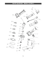
Page 19: ...19 PARTS DIAGRAM MODEL 39 9049 2 ...

Page 20: ...ck cover 1 6 242555 Fixing steel wire 1 7 654503 Battery pack 2 8 222251 Conducting strip 4 9 152005 Contact plate 1 10 N A Lead wire 2 11 130032 Motor 1 12 200058 Motor gear 1 13 202011 Oil retaining bearing 1 14 232509 Gear box 1 15 340011 Sealing ring 1 16 312136 Gear box cover 1 17 500209 Screw 4 18 200059 Gear 1 19 202712 Shaft 1 20 520026 Bearing 1 21 321025 Vibration reduction ring 1 22 341...

Reviews: