


User manual for universal counter with batching function SLIK-73
4.3.
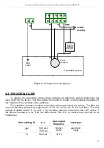
CONNECTION METHOD
Caution
- Installation should be conducted by qualified personnel . During installation all
available safety requirements should be considered. The fitter is responsible for
executing the installation according to this manual, local safety and EMC
regulations.
- The unit is not equipped with an internal fuse or power supply circuit breaker.
Because of this an external time-delay cut-out fuse with minimal possible nominal
current value must be used (recommended bipolar, max. 2A) and a power supply
circuit-breaker located near the unit. In the case of using a monopolar fuse it must
be mounted on the phase cable (L).
- The power supply network cable diameter must be selected in such a way that in
the case of a short circuit of the cable from the side of the unit the cable shall be
protected against destruction with an electrical installation fuse.
- Wiring must meet appropriate standards and local regulations and laws.
- In order to secure against accidental short circuit the connection cables must be
terminated with appropriate insulated cable tips.
- Tighten the clamping screws. The recommended tightening torque is 0.5 Nm.
Loose screws can cause fire or defective operation. Over tightening can lead to
damaging the connections inside the units and breaking the thread.
- In the case of the unit being fitted with separable clamps they should be inserted
into appropriate connectors in the unit, even if they are not used for any
connections.
- Unused clamps (marked as n.c.) must not be used for connecting any
connecting cables (e.g. as bridges), because this can cause damage to the
equipment or electric shock.
- If the unit is equipped with housing, covers and sealing packing, protecting
against water intrusion, pay special attention to their correct tightening or clamping.
In the case of any doubt consider using additional preventive measures (covers,
roofing, seals, etc.). Carelessly executed assembly can increase the risk of electric
shock.
- After the installation is completed do not touch the unit’s connections when it is
switched on, because it carries the risk of electrical shock.
Due to possible significant interference in industrial installations appropriate measures
assuring correct operation of the unit must be applied. To avoid the unit of improper
indications keep recommendations listed below.
–
Avoid common (parallel) leading of signal cables and transmission cables together with
power supply cables and cables controlling induction loads (e.g. contactors). Such cables
should cross at a right angle.
–
Contactor coils and induction loads should be equipped with anti-interference protection
systems, e.g. RC-type.
8
!


