Supplied By www.heating spares.co Tel. 0161 620 6677
12
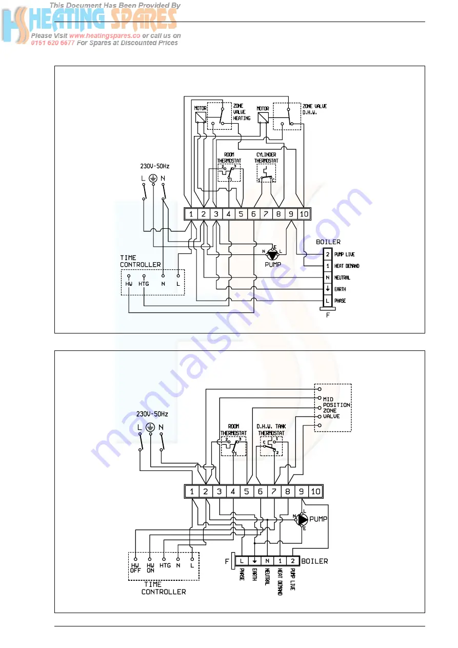
Fig. 18
FULLY PUMPED SYSTEM USING TWO ZONE VALVES
Fig. 19
FULLY PUMPED SYSTEM USING MID POSITION ZONE VALVE
Page 1: ...Supplied By www heating spares co Tel 0161 620 6677 Superior Ci Installation Servicing Instructions GB PLEASE LEAVE THIS INSTRUCTION WITH THE USER ...
Page 2: ...nce with the guidelines given in BS7593 Treatment of water in domes tic hot water central heating systems Is the system and boiler full of water Is the gas supply working pressure correct Is the boiler wired correctly See installation manual Has the customer been fully advised on the correct use of the boiler system and controls Has the log book provided been completed CONTENTS 1 TECHNICAL FEATURE...
Page 3: ... additional flue elbow may he fitted The boiler is designed for use with sealed and gravity primary water systems and is supplied fully assembled and complete with compression joints for simple connection to the heating system The boiler can be used with a 230V room thermostat class II according to EN 60730 1 1 1 TECHNICAL FEATURES AND DIMENSIONS 1 2 DIMENSIONAL DETAILS Fig 1 TABLE 2 Minimum clear...
Page 4: ... 0 47 700 15 4 17 1 58 200 13 6 5 5 14 3 48 700 15 7 17 4 59 300 14 1 5 7 X 14 6 49 700 16 0 17 8 60 500 14 7 5 9 Factory setting TABLE 3c Nominal boiler ratings 2 minutes after lighting for Superior 60 Ci MODE OUTPUT INPUT N C V INPUT G C V BURNER PRESSURE kW Btu h kW kW Btu h mbar inwg CENTRAL HEATING RANGE 14 7 50 000 16 4 18 2 62 000 10 4 4 2 15 0 51 000 16 7 18 5 63 100 10 8 4 3 15 3 52 100 1...
Page 5: ... 84 84 84 Boiler pressure drop t 11 C mbar 100 150 220 330 Electricity Supply 230V 50Hz Internal Fuse F 2A Power Consumption W 55 55 60 65 Weight kg 46 46 46 57 TABLE 4 General specifications 17 3 4 6 7 1 8 5 2 9 16 10 11 12 13 14 15 1 4 INTERNAL VIEW KEY 1 Air pressure switch 2 Safety stat 105 C 3 Positive pressure test point 4 Negative pressure test point 5 Thermistor 6 Fan 7 Cast iron heat exch...
Page 6: ...d provided it is modified accordingly Where installation will be in an unusual location special procedures may be necessary BS6798 gives detailed gui dance on this aspect 2 3 FLUE TERMINAL POSITION Detailed recommendations for flue installation are given in BS5440 1 The following notes are for general guidance The boiler MUST be installed so that the terminal is expo sed to the external air It is ...
Page 7: ...to maintain an 11 C temperature rise between the pumped flow and return pipes connected to the appliance Details of the appliance pressure drop are provided in Table 4 System drain cocks should be fitted at the lowest points in the system in order to provide adequate drain points BS5442 pro vides information for the protection of the boiler due to freezing A frost thermostat should be fitted to th...
Page 8: ...vided which incorporates a stopcock Provision should be made to replace system water losses by either pre pressurising the system or fitting a make up vessel at the highest point of the system BS 5376 pt2 1976 2 8 5 Fully pumped The heating system design should be based on the following information The appliance pressure drop details are given in Table 4 A minimum flow rate corresponding to a heat...
Page 9: ...heating pipes should be 22 mm diame ter and be connected to each of the 22 mm connections on the flow and return manifolds A gravity system requires a minimum circulating head of 1 m assuming there is no hori zontal pipe run If horizontal pipe runs are required then an increase in head of 0 5 m is required for every additional 1 m of horizontal pipe Further details are available in the current iss...
Page 10: ...de 8084804 is requi red with reference to the Z dimension shown in figs 10 13 If any extensions are required the flue and air ducts should be joined before proceeding to the next section The exten sion ducts should be joined to each other and to the standard ducts using the following procedure fig 9 For the flue ducts in turn push the plain end of the stan dard and if using two or three extensions...
Page 11: ...rence to fig 13 slide on the aluminium retention ring D check that the rubber sealing ring E is pulled up to the wall and that the duct assembly is horizontal then secure the aluminium retention ring to the air duct using the two screws H provided Do not overtighten the screws Push the junction collar B over the air duct until the air duct touches the inner part of the collar where the diame ter b...
Page 12: ... case at the top rear right hand cor ner These are for the pumped side of a combined system or a fully pumped system If the appliance is to be installed on a combined system the two 28 mm connections must be used for the gravity flow and return the system may be connected directly to the 28 mm compression fittings on the boiler manifolds by means of the olives provided Street elbows should be used...
Page 13: ...ms COMBINED PUMPED CH GRAVITY D H W Fig 17 Fully pumped or combined pumped and gravity operation The appliance is supplied ready for installation within a fully pumped heating hot water system If the appliance is to be installed within a combined pumped and gravity system the switch on the rear of the control box should be set to gravity see fig 16 ...
Page 14: ...Supplied By www heating spares co Tel 0161 620 6677 12 Fig 18 FULLY PUMPED SYSTEM USING TWO ZONE VALVES Fig 19 FULLY PUMPED SYSTEM USING MID POSITION ZONE VALVE ...
Page 15: ...ed correctly Balance the flow rates through the boiler radiators and hot water cylin der The complete system should now be allowed to heat to maximum and a final check completed Turn off the system and drain for the final time Refill and vent the system completely Set the boiler and external controls to a suitable setting 4 2 ADDITIONAL OPERATIONS FOR SEALED SYSTEMS Whilst the system is empty and ...
Page 16: ... of their respective position Slide the burner forwards and at the same time feed the two wires through the grommet in the sealed chamber Remove the burner complete with the electrodes and leads Inspect and if necessary clean the electrodes and the main burner bars Inspect the main injector for any signs of damage or debris and clean if necessary 5 2 FAN ASSEMBLY Disconnect the electrical connecti...
Page 17: ... fault NOTE Should it be found that the fuse has failed but no fault is indicated a detailed continuity check i e by discon necting and checking each component is required to trace the faulty component It is possible that a fault could occur as a result of local bur ning arcing but no fault could be found under test However a detailed visual inspection should reveal evidence of burning around the ...
Page 18: ...es Fault Fault Satisfactory Does the gas valve open and allow gas to the main burner injector Is there a spark between the ignitor and the burner Yes Operation normal Replace assembly Yes Is there 230 V at the fan motor Yes Check the wiring and rectify No Check the spark gap and rectify No No No Disconnect fan leads from fan motor Is there between 30 60 ohms across fan motor Replace the ignition d...
Page 19: ...Supplied By www heating spares co Tel 0161 620 6677 17 7 WIRING DIAGRAM AND INTERNAL VIEW 7 1 FUNCTIONAL FLOW WIRING DIAGRAM Fig 23 ...
Page 20: ...and pulling the panel forwards lifting it off the two pins at the top two corners Unscrew the screw retaining the cover of the control box unplug the connector and remove the control box Replace it and re assemble in reverse order 8 5 ELECTRONIC PCB Remove the casing by unscrewing the retaining screws at bottom rear of the appliance and pulling the panel forwards lifting it off the two pins at the...
Page 21: ...an downwards and once disengaged from the flue turret remove it forwards Replace the fan and re assemble in reverse order 8 12 BURNER VIEWING WINDOW Remove the casing by unscrewing the retaining screws at bottom rear of the appliance and pulling the panel forwards lifting it off the two pins at the top two corners Remove the 4 fixing screws securing the sealed chamber front panel then remove the p...
Page 22: ...n section 32 2005000 Self threading screw Hex H M5x10 33 6229213 Fan mounting plate 40 50 33 A 6229215 Fan mounting plate 60 33 B 6229214 Fan mounting plate 80 34 2016020 Locked nut M4 35 6225617 Fan 40 50 35 A 6225618 Fan 60 35 B 6225619 Fan 80 36 2000705 Screw M4x12 37 6229103 Terminal strip bracket Position Code Description Model 38 6229101 Smoke pressure switch bracket 39 6225713 Air pressure ...
Page 23: ...ve for pipe Ø 28 83 6177505 Ball cock 3 4 x 22 84 2030228 Gasket Ø 17x24x2 85 6289720 Pipe connecting manifold cock 40 50 60 85 A 6289721 Pipe connecting manifold cock 80 86 6291500 Gasket for manifold flange 40 50 60 86 A 6291501 Gasket for manifold flange 80 Recommended stock parts Position Code Description Model 37 6229103 Terminal strip bracket 61 6286901 Control panel lower part 62 6286801 Co...
Page 24: ...ting spares co Tel 0161 620 6677 Cod 6274228 Documentation Dpt Sime Ltd Unit D2 Enterprise Way Bradford Road Bradford West Yorkshire BD10 8EW Tel 0870 9911114 Fax 0870 9911115 www sime ltd uk e mail enquiries sime ltd uk ...