8.6
GAS VALVE
– Remove the outer casing as described in section 5.1.
– Disconnect the electrical connections to the gas valve.
– Unscrew the pilot pipe connector.
– Unscrew the burner manifold union.
– Unscrew the four posi-head screws securing the gas
valve inlet pipe, and remove the gas valve complete with
the outlet pipe.
– Transfer the outlet pipe onto the new gas valve, using a
new gasket (supplied with the valve).
– Fit the new gas valve assembly into the appliance using
the other new gasket supplied on the valve inlet, and re-
assemble in reverse order.
– Relight the appliance, check for gas soundness, and
recommission in accordance with section 4.
In addition it will be necessary to set the D.H.W. and
C.H. heat inputs, as follows:
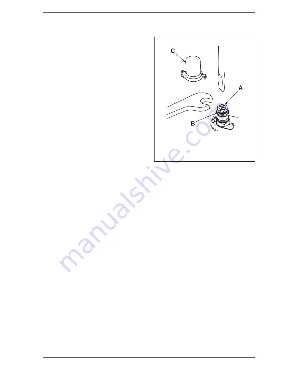
– remove the sealing cap of the proportioning unit (C
fig. 27) by rotating it ⁄ turn anticlockwise;
– using a 10 mm spanner, turn nut (B fig. 27) to attain
the following required D.H.W. max. burner pressures:
- 12.9 mbar (5.2 inwg) for
“SUPER 90”
;
- 12.7 mbar (5.1 inwg) for
“SUPER 102”
.
Turn the nut clockwise to increase the pressure or
anti-clockwise to decrease it;
– check that the maximum pressure is correctly set by
turning on and off the D.H.W. inlet valve several times
and ensuring that the pressure returns to that pre-
viously adjusted;
– isolate the mains electricity supply and disconnect
(pull off) the two 24 V modulation leads (fig. 16).
Restore the mains supply. The appliance will light on
minimum input only;
– set the minimum pressure of 1.5 mbar (2.0 mbar for
“SUPER 102”
) by holding nut (B fig. 27) in position
with a 10 mm spanner and rotating the plastic screw
(A fig. 27) with a screwdriver until the correct pressure
is obtained.
Turn the screw clockwise to increase the pressure or
anti-clockwise to decrease it. It is essential that the
max pressure has been set prior to adjusting the mini-
mum pressure.
Check that the minimum pressure is correctly set by
turning on and off the D.H.W. inlet valve several times
and ensuring that the pressure returns to that pre-
viously adjusted;
– isolate the mains electricity supply and reconnect
(push on) the two 24 V modulation leads (polarity is
immaterial).
Restore the mains supply. The appliance will light on
maximum input.
Check that the burner pressure corresponds to the
values given in the previous points;
– refit the proportioning unit sealing cap (C fig 27);
– reduce the D.H.W. draw off rate to the minimum
necessary to maintain the burner alight by carefully
adjusting the D.H.W. Inlet valve and check that the
burner pressure decreases in response to D.H.W. tem-
perature rise.
Fully open the inlet valve;
– close the D.H.W. tap and ensure that the burner is
extinguished and the pump stops.
– Continue as in section 4.3 to 4.5.
8.7
PRESSURE SWITCH
Two types of pressure switch are available on this
appliance, HONEYWELL or HUBA. Both are fully inter-
changeable, and figs. 21 - 22 shows the differences
between them. Note that the HUBA switch has a
bracket not required by the HONEYWELL switch.
– Remove the outer casing and the sealed chamber front
panel as described in section 5.1.
– Disconnect the pressure sensing pipes from the switch
(fig. 20).
– Disconnect the electrical connections from the switch.
– Unscrew and remove the two screws securing the moun-
ting bracket (HUBA) or switch body (HONEYWELL).
– (HUBA only) Remove the switch from the bracket (two
screws) and fit the new one.
– Fit the new switch and re-assemble in reverse order
referring to figs. 21 - 22 and the wiring diagrams (sec-
tion 7) as appropriate.
8.8
LIMIT THERMOSTAT
The limit thermostat is situated on the top, L.H.S. of the
heat exchanger (18 fig. 24).
– Remove the outer casing and the sealed chamber front
panel as described in section 5.1.
– Without disconnecting the wires, unscrew the two limit
thermostat fixing screws.
– Lift the thermostat and fixing screws out using the wires.
– Replace the thermostat and spread heat sink compound
(supplied) over the base of the new one. Connect the
wires, (polarity is immaterial) and position the screws in
the flange and re-fit using the wires to position the ther-
mostat before tightening the screws.
– Re-assemble in reverse order.
26
Fig. 27
KEY
A
Plastic screw
B
Nut
C
Sealing cap


