47
EN
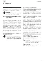
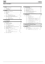
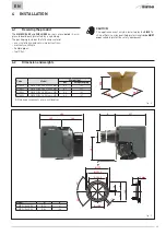
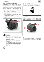
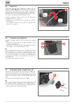
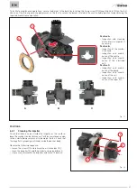
To mount the burner on the boiler:
– couple the seal (1) and the flange (2), both supplied with the
product;
1
2
Fig. 13
– position the flange (2), with the fixing screw (3) on top and lock
it with the nuts (4) provided;
– tighten the nuts (4) adequately diagonal-wise;
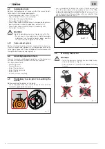
– insert the combustion head (5) of the burner inside the flange
(2);
3
4
2
5
6
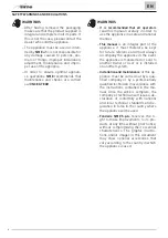
Fig. 14
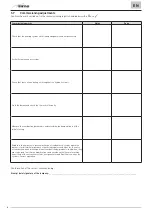
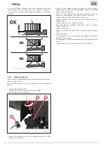
– turn the burner slightly, first towards the right then towards
the left, to properly position the fixing screw (3) in its housing
(6);
– press the burner against the boiler and tighten the fixing
screw (3) to lock it in place;
3
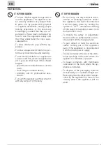
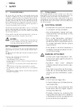
Fig. 15
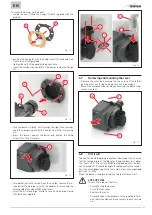
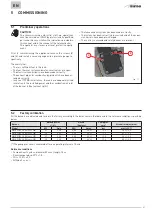
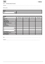
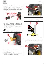
– for applications with suction from the outside, remove the in-
take grille (7) and replace it with the adapter for mounting the
external pipe (8) code 6290502 (optional)
– insert the air intake pipe (9) and secure it using a pipe clamp
(10), both not supplied.
9
7
8
10
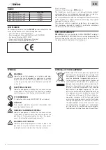
Fig. 16
4.7
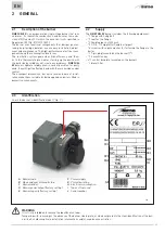
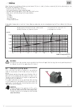
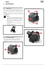
Removing and mounting the cover
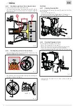
– Remove the cover by loosening the two screws (1) and then
pull the cover out (2) while taking care not to damage it.
– Mount the component back on by performing the above steps
in reverse order.
2
1
1
Fig. 17
4.8
Oil circuit
The fuel tank and the piping layout must be made in such a way
that the temperature of the diesel entering the burner is equal
to at least +5°C. The system MUST be topped up with the bur-
ner switched off. It should be kept off subsequently for around 1
hour to ensure degassing of the fuel and to allow any suspended
particles to settle.
When the burner is replaced, replace the fuel filter as well.
a
LOSS OF FUEL
In case of accidental fuel loss:
– Promptly stop the burner
– Close the fuel valves
– Ventilate the room
– Promptly report the problem to the qualified Tech-
nical Service and have the necessary repairs carried
out.

