


The boiler must be installed in a fixed loca-
tion and only by specialized and qualified per-
son in compliance with all instructions con-
tained in this manual. Furthermore, the
installation must be in accordance with cur-
rent standards and regulations.
2.1
VENTILATION REQUIREMENTS
Detailled recommendations for air supply
are given in BS5440:2. The following notes
are for general guidance: it is not necessary
to have a purpose provided air vent in the
room or compartment in which the appliance
is installed.
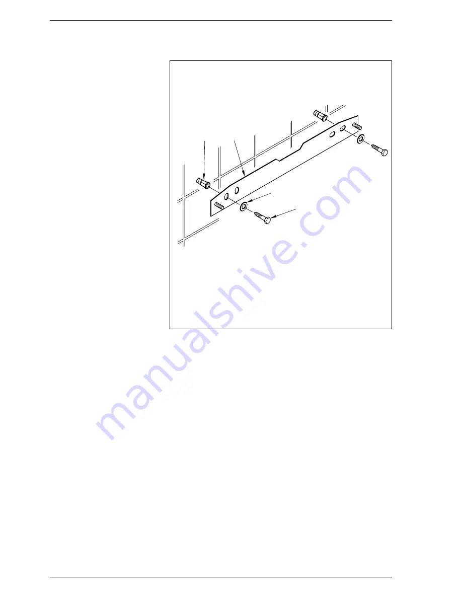
2.2
FIXING THE WALL
MOUNTING BRACKET
– Mark the position of the two wall mount-
ing bracket fixing holes and the flue/air
duct hole on the appropriate wall(s).
– Drill the top two fixing holes using a 10
mm masonry drill and fit the plastic
plugs provided.
– Cut the hole in the wall for the flue/air
duct. The diameter should not be less than
100 mm (4 in) and must be horizontal. If
the hole is not accessible from the outside
of the building, its minimum diameter
should be sufficient to allow the insertion of
the wall liner (130 mm - 5
1
/
4
in diameter)
which will be sealed with mortar.
– Accurately measure the wall thickness,
and note this dimension for later use.
– Secure the wall mounting bracket in
position using the screws provided.
Ensure that it is the correct way up, as
indicated in fig. 4.
2.3
CONNECTING UP SYSTEM
Before proceeding to connect up the boiler,
you are recommended to flush out the sys-
tem in order to eliminate any foreign bodies
that might be detrimental to the operating
efficiency of the appliance. When making
the hydraulic connections, make sure that
the clearences indicated in fig. 1 are
respected. To facilitate the hydraulic con-
nections the boiler is equipped with a valve
pack code 5184803 complete with instruc-
tions sheet.
A safety valve set at 3 bar is fitted to the
appliance, the discharge pipe provided
should be extended to terminate safely away
from the appliance and where a discharge
would not cause damage to persons or prop-
erty but would be detected. The pipe should
be a minimum of 15 mm Ø and should be
able to withstand boiling water, any should
avoid sharp corners or upward pipe runs
where water may be retained.
The gas connection must be made using
seamless
steel
or
copper
pipe
(Mannesmann type), galvanized and with
threaded joints provided with gaskets,
excluding three-piece connections, except
for initial and end connections. Where the
piping has to pass through walls, a suitable
insulating sleeve must be provided. When
sizing gas piping, from the meter to the boil-
er, take into account both the volume flow
rates (consumption) in m
3
/h and the rela-
tive density of the gas in question. The sec-
tions of the piping making up the system
must be such as to guarantee a supply of
gas sufficient to cover the maximum
demand, limiting pressure loss between the
gas meter and any apparatus being used to
not greater than 1.0 mbar for family II
gases (natural gas). An adhesive data badge
is sited inside the front panel; it contains all
the technical data identifying the boiler and
the type of gas for which the boiler is
arranged.
2.3.1
Connection of condensation
water trap
The drip board and its water trap must be
connected to a civil drain through a pipe
with a slope of at least 5 mm per metre to
ensure drainage of condensation water.
The plastic pipes normally used for civil
drains are the only type of pipe which is
appropriate for conveying condensation
to the building’s sewer pipes.
2.3.2
Requirements for
sealed water systems
The heating system design should be based
on the following information:
a) The available pump head is given in fig. 16.
b) The appliance is equipped with an inter-
nal by-pass that operates with system
heads (H) greater than 3 m. The maxi-
mum flow through the by-pass is about
300 l/h. If thermostatic radiator valves
are to be installed, at least one radiator
should be without a thermostatic valve
(usually the bathroom radiator).
2.4
CHARACTERISTICS
OF FEEDWATER
– All recirculatory systems will be subject
to corrosion unless an appropriate
water treatment is applied. This means
that the efficiency of the system will
deteriorate as corrosion sludge accu-
mulates within the system, risking dam-
age to pump and valves, boiler noise
and circulation problems.
– For optimum performance after instal-
1
2
3
4
5
2INSTALLATION
Fig. 4
KEY
1
Wall mounting bracket
2
Plastic wall plug (2 Off)
3
Woodscrew (2 Off)
4
Washer (2 Off)
Summary of Contents for Format System 25 HE
Page 1: ...Format System 25 HE Installation and servicing instructions GB ...
Page 21: ...19 7 EXPLODED VIEWS Fig 24 Position Code Description Model 7 1 HYDRAULIC CIRCUIT ...
Page 22: ...20 Position Code Description Model 7 2 COMBUSTION CIRCUIT Fig 24 a ...
Page 23: ...21 7 3 STRUCTURAL COMPONENTS AND CONTROL REGULATIONS Position Code Description Model Fig 24 b ...
Page 25: ...Format System 25 HE User instructions GB PLEASE LEAVE THIS INSTRUCTION WITH THE USER ...
Page 26: ......