SIME FORMAT WALL HUNG BOILERS
MODEL 34i AND MODEL 34e
REF: INSTALLATION INSTRUCTIONS
19/02/04
9
2.3 Flueing
2.3.1
The flue system for the Model 34i is by 60/100 mm dia co-axial
flue components. It can be applied horizontally to the rear of the
boiler, to either side, and vertically by means of a custom-designed
flue terminal.
2.3.2
The maximum length for both horizontal and vertical systems is
3 metres.
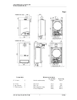
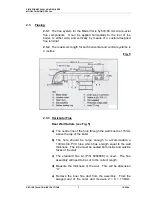
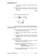
Fig. 5
2.3.3 Horizontal
Flue
Rear Wall Outlets (see Fig. 5)
a)
The centre line of the hole through the wall must be 115mm
above the top of the boiler.
b)
The hole should be large enough to accommodate a
130mm dia PVC tube, which has a length equal to the wall
thickness. The tube must be sealed both inside and outside
faces of the wall.
c)
The standard flue kit (P/N 8084808) is used. The flue
assembly will need to be cut to the correct length.
d)
Measure the thickness of the wall. This will be dimension
“X”.
e)
Remove the inner flue duct from the assembly. From the
swaged end of the outer duct measure Z = X + 130mm.


