2.9
HYDRAULIC SEPARATOR
2.9.1
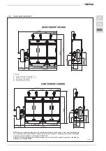
DEWY EQUIPE
60-120-180-240 BOX
P60-P120 BOX
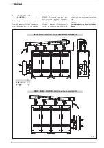
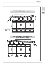
The hydraulic separator is supplied separa-
tely in a kit code 8101550 complete with
gaskets, nuts and fastening screws (figure
8).
WARNING: The hydraulic separator can
be inserted in a specific protective case
code 8101517 supplied separately.
2.9.2
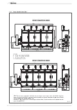
DEWY EQUIPE 300-360 BOX
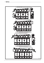
The hydraulic separator is supplied separa-
tely in a kit code 8101551 complete with
gaskets, nuts and fastening screws (figure
8/a).
WARNING: The hydraulic separator can
be inserted in a specific protective case
code 8101517 supplied separately.
2.9.3
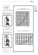
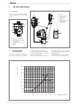
Load loss
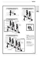
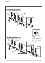
Hydraulic separator load losses are indica-
ted in the diagram in fig. 9.
75
IT
ES
ENG
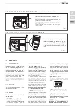
Fig. 8
80
100
120
140
2
PORTATA (m3/h)
4
6
8
10
12
0
20
40
60
∆
p (mbar)
14
16
18
160
180
200
220
240
260
Fig. 9
CAPACITY (m
3
/h)
Hiydraulic separator
“DEWY EQUIPE 60-120-180-240 BOX/P60-P120 BOX”
Hiydraulic separator “DEWY EQUIPE 300-360 BOX”
20
25
30
35
2
PORTATA (m
3
/h)
4
6
8
10
12
0
5
10
15
∆
p (mbar)
14
Dewy Equipe 300-360 B
O
X
40
16
18
CAPACITY (m
3
/h)
Fig. 8/a
Summary of Contents for DEWY EQUIPE 120 BOX
Page 2: ......
Page 88: ......
Page 89: ...TAGLIARE LUNGO LA LINEA TRATTEGGIATA ...
Page 90: ......
Page 91: ......

