8.6
GAS VALVE
– Remove the casing front panel as described in section 5.1.
– Unscrew the single screw securing the plastic ignition
control box to the gas valve and pull off the control box in
a forwards direction.
– Disconnect the two leads from the modulating solenoid.
– From underneath the appliance, unscrew the four posi-
head screws securing the gas valve inlet pipe flange.
– Remove the two screws securing the control box and
pivot the control box downwards
– Unscrew the burner manifold nut underneath the
sealed casing, and withdraw the gas valve complete
with outlet pipe.
– Transfer the outlet pipe onto the new gas valve, using a
new gasket (supplied with the valve).
– Fit the new gas valve assembly into the appliance using
the other new gasket supplied on the valve inlet, and re-
assemble in reverse order.
– Re-light the appliance, check for gas soundness, and re-
commission in accordance with section 4.
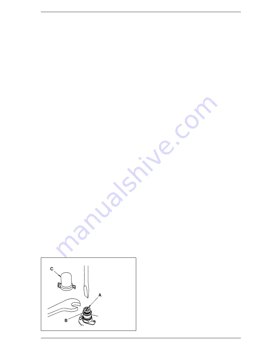
In addition it will be necessary to set the D.H.W. and C.H.
heat inputs, with reference to fig. 28, as follows: (SIT gas
valve). Note that it is necessary to set the MAXIMUM PRES-
SURE FIRST.
– Connect a pressure gauge to the burner pressure
test point.
– Remove the sealing cap of the proportioning unit (C) by
rotating it ⁄ turn anticlockwise.
– Adjust DHW potentiometer to maximum, then fully open
any DHW tap to light the boiler.
– Using a 10 mm spanner, turn nut (B) to attain the maxi-
mum pressure in
Table 3.
Turn the nut clockwise to increase or anti-clockwise to
decrease the burner pressure.
– Turn the main selector switch on and off a few times (with
the hot tap still open) and check that the pressure returns
to the correct (set) maximum value (as in
Table 3).
– Set the minimum burner pressure by first isolating the
electricity supply and disconnecting one of the modulat-
ing solenoid leads, then restore the electricity supply and
fully open a DHW tap to light the appliance at minimum
gas rate.
– Set the minimum pressure of 1.5 mbar by holding nut (B)
in position with a 10 mm spanner and rotating the plastic
screw (A) with a screwdriver until the correct pressure is
obtained. Turn the screw clockwise to increase the pres-
sure or anti-clockwise to decrease it. It is essential that
the max pressure has been set prior to adjusting the mini-
mum pressure. Check that the minimum pressure is cor-
rectly set by turning on and off the D.H.W. inlet valve sev-
eral times and ensuring that the pressure returns to that
previously adjusted;
– Isolate the power supply, re-connect the modulation lead,
restore the power and re-check the maximum pressure,
then re-fit the plastic cover (1).
– Reduce the D.H.W. draw off rate to the minimum nec-
essary to maintain the burner alight by carefully adjusting
the D.H.W. Inlet valve and check that the burner pressure
decreases in response to D.H.W. temperature rise. Fully
open the inlet valve;
– Close the D.H.W. tap and ensure that the burner is extin-
guished and the pump stops.
– Adjust the Central Heating maximum pressure as
described in section 4.3, then complete the re-commis-
sioning as described in 4.4 and 4.5.
8.7
AIR PRESSURE SWITCH
– Remove the casing front panel and sealed chamber front
panel as described in section 5.1.
– Disconnect the pressure sensing pipe from the switch.
– Unscrew and remove the two screws securing the mount-
ing bracket.
– Remove the switch from the bracket (two screws) and fit
the new one.
– Transfer the electrical connections one at a time (to
ensure that they are not incorrectly re-fitted) to the new
switch.
– Re-assemble in reverse order referring to the wiring dia-
grams (section 7) if necessary. Ensure that the pressure
sensing lead is correctly connected to the low pressure
connection on the pressure switch (marked P2).
8.8
LIMIT THERMOSTAT
The limit thermostat is situated on the top, R.H.S. of the heat
exchanger (12 fig. 26).
– Remove the outer casing and the sealed chamber front
panel as described in section 5.1.
– Without disconnecting the wires, unscrew the two limit
thermostat fixing screws.
– Lift the thermostat and fixing screws out using the wires.
– Replace the thermostat and spread heat sink compound
(supplied) over the base of the new one. Connect the
wires, (polarity is immaterial) and position the screws in
the flange and re-fit using the wires to position the ther-
mostat before tightening the screws.
– Re-assemble in reverse order.
8.9
OVERHEAT THERMOSTAT
The overheat thermostat is situated on the flow pipe, below
the sealed chamber (10 fig. 26).
– Remove the casing front panel as described in section 5.1.
– Disconnect the two overheat thermostat wires.
– Unscrew the two limit thermostat fixing screws and
remove the thermostat.
24
KEY
A
Plastic screw
B
Nut
C
Sealing cap
Fig. 28
Summary of Contents for benchmark FRIENDLY FORMAT
Page 1: ...Friendly Format Installation and servicing instructions GB ...
Page 33: ...Friendly Format User instructions GB ...
Page 34: ......
Page 39: ......


