Smart Machine Smart Decision
SIM68R_Hardware Design_V1.02
25
2013-01-22
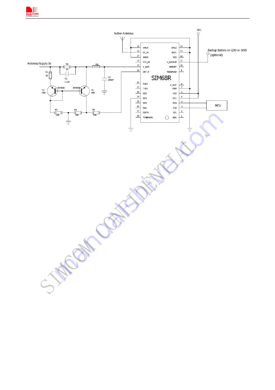
Figure 12: Open circuir detection-B
If the antenna supply voltage is not derived from VCC_RF, do not exceed the maximum voltage rating of DET_N.(5V)
Page 1: ...SIM68R_Hardware Design_V1 02 ...
Page 2: ...e customer s possession Furthermore system validation of this product designed by SIMCom within a larger electronic system remains the responsibility of the customer or the customer s system integrator All specifications supplied herein are subject to change Copyright This document contains proprietary technical information which is the property of SIMCom Limited copying of this document and givin...
Page 3: ...R Start 16 4 1 4 Power Saving Modes 16 4 1 5 Operating Mode 17 4 1 5 1 Full on Mode 17 4 1 5 2 Sleep Mode 17 4 1 6 VCC_RF 17 4 2 UART Interface 17 4 3 I2 C interface 18 4 4 Timemark Output 18 4 5 DET_N 18 4 6 A GPS 18 4 6 1 EPO 18 4 6 2 EASY MODE 19 4 6 3 SBAS and RTCM 19 4 7 GNSS Antenna 19 4 7 1 Antenna Interface 20 4 7 2 GNSS Antenna Choice Consideration 20 4 7 2 1 Passive Antenna 20 4 7 2 2 Ac...
Page 4: ...atic Discharge 27 5 4 Certification 27 6 Manufacturing 28 6 1 Top and Bottom View of SIM68R 28 6 2 Assembly and Soldering 28 6 3 Moisture sensitivity 29 6 4 ESD handling precautions 30 6 5 Shipment 30 7 Reference Design 31 Appendix 32 A Related Documents 32 B Terms and Abbreviations 32 ...
Page 5: ...LE 5 HOST PORT MULTIPLEXED FUNCTION PINS 18 TABLE 6 ANTENNA SPECIFICATIONS 19 TABLE 7 ABSOLUTE MAXIMUM RATINGS 26 TABLE 8 SIM68R OPERATING CONDITIONS 26 TABLE 9 SIM68R STANDARD IO FEATURES 26 TABLE 10 THE ESD ENDURE STATUE MEASURED TABLE TEMPERATURE 25 HUMIDITY 45 27 TABLE 11 ILLUSTRATION OF MODULE INFORMATION 28 TABLE 12 MOISTURE CLASSIFICATION LEVEL AND FLOOR LIFE 29 TABLE 13 RELATED DOCUMENTS 3...
Page 6: ...N 21 FIGURE 6 SIM68R PASSIVE ANTENNA DESIGN WITH EXTERNAL LNAAND SAW 21 FIGURE 7 SIM68R PASSIVE ANTENNA DESIGN FOR BEST PERFORMANCE 22 FIGURE 8 SIM68R ACTIVE ANTENNA DESIGN 22 FIGURE 9 INTERNAL SUPPLY ANTENNA BIAS VOLTAGE 23 FIGURE 10 EXTERNAL SUPPLY ANTENNA BIAS VOLTAGE 23 FIGURE 11 OPEN CIRCUIR DETECTION A 24 FIGURE 12 OPEN CIRCUIR DETECTION B 25 FIGURE 13 TOP AND BOTTOM VIEW OF SIM68R 28 FIGURE...
Page 7: ...ecision SIM68R_Hardware Design_V1 02 32 2013 01 22 Version History Date Version Description of change Author 2012 10 17 V1 00 Origin Shengwu Sun Xiaohan Jin 2013 01 22 V1 02 Add some features and Modify pictures Shengwu Sun ...
Page 8: ...ut navigation solution in NMEA protocol format The module requires 2 8V 4 3V power supply The host port is configurable to UART Host data and I O signal levels are 2 85V CMOS compatible z GPS GLONASS Galileo receiver supports multi GNSS include QZSS SBAS ranging supports WAAS EGNOS MSAS GAGAN z 33tracking 99 acquisition channel GNSS receiver z Small footprint 17 x 22 4x 2 7mm 28 pin LCC package z ...
Page 9: ... signals Figure 1 SIM68R functional diagram 2 2 GNSS Performance Table 1 GNSS performance SIM68R_Hardware Design_V1 02 9 2013 01 22 Performance Parameter Description Min Type Max Unit Horizontal Position Accuracy 1 Autonomous 2 5 m Without Aid 0 1 m s Velocity Accuracy 2 DGPS 0 05 m s Without Aid 0 1 m s2 Acceleration Accuracy DGPS 0 05 m s2 Timing Accuracy 10 nS Maximum Altitude 18000 m Maximum V...
Page 10: ...eep current 440 uA Power consumption A 4 Backup current 14 uA 1 50 24hr static 130dBm 2 50 at 30m s 3 130 dBm GPS GLONASS mode 4 Single Power supply 3 3V under GPS GLONASS signal 2 3 General features Table 2 General features Parameters Value Supply voltage VCC 2 8V 4 3V Supply voltage ripple VCC 54 mV RMS max f 0 3MHz 15 mV RMS max f 3 MHz Power consumption acquisition 37mA type VCC 3 3 V Power co...
Page 11: ...2 C Serial port protocol UART NMEA 8 bits no parity 1 stop bit 115200 baud configurable TM output 1PPS 1 pulse per second synchronized at rising edge pulse length 300ms Note 1 Operation in the temperature range 40 C 30 C is allowed but Time to First Fix performance and tracking sensitivity may be degraded ...
Page 12: ...scription Table 3 Pin description Pin name Pin number I O Description Comment Power supply VCC 6 I Main power input which will be used to power the baseband and RF section internally Provide clean and stable power source to this pin Add a 4 7uF capacitor to this pin for decoupling SIM68R_Hardware Design_V1 02 12 2013 01 22 ...
Page 13: ...erial input If unused keep open TXD1 22 O Serial output as RTCM RXD1 21 I Serial input as RTCM GPIOs EINT0 27 I This interrupt source could act as wake up event during power saving mode Provide an interrupt on either high or low logic level or edge sensitive interrupt Not supported yet keep open TIMEMARK 28 O Time Mark outputs timing pulse related to receiver time If unused keep open NRESET 10 I R...
Page 14: ...art Decision 3 3 Package Dimensions Following figure shows the Mechanical dimensions of SIM68R top view side view and bottom view Figure 3 SIM68R mechanical dimensions Unit mm SIM68R_Hardware Design_V1 02 14 2013 01 22 ...
Page 15: ...Smart Machine Smart Decision 3 4 SIM68R Recommended PCB Decal Figure 4 Recommended PCB decal top view Unit mm SIM68R_Hardware Design_V1 02 15 2013 01 22 ...
Page 16: ...mmand through the communication interface or external interrupt z Backup mode In this mode the SIM68R must be supplied by the backup and it can help to count down the time for backup mode Software on host side to send the command through the communication interface into the backup mode z Periodic mode In this mode the SIM68R enters tracking and backup mode according to the interval configured by u...
Page 17: ...igital baseband and RF are internally powered off The power supply input VCC shall be kept active all the time even during sleep mode Entering into sleep mode is sent PMTK command through the communication interface by host side Waking up from sleep mode is sent any byte through the communication interface by host side 4 1 6 VCC_RF VCC_RF is a 2 8V output for external active antenna if the externa...
Page 18: ... antenna or not Low level means the antenna has been detected High level means no external antenna has been detected NOTE The High level for DET_N should be 2 85V CMOS level 4 6 A GPS A GPS is the meaning of Assisted GPS which is a system that can under certain conditions improve the startup performance or time to first fix TTFF of a GPS satellite based positioning system SIM68R module supports EP...
Page 19: ... System The SBAS concept is based on the transmission of differential corrections and integrity messages for navigation satellites that are within sight of a network of reference stations deployed across an entire continent SBAS messages are broadcast via geostationary satellites able to cover vast areas Several countries have implemented their own satellite based augmentation system Europe has th...
Page 20: ...obtain excellent GNSS receiving performance a good antenna will always be required The antenna is the most critical item for successful GNSS receiving in a weak signal environment Proper choice and placement of the antenna will ensure that satellites at all elevations can be seen and therefore accurate fix measurements are obtained 4 7 2 1 Passive Antenna Passive antenna contains only the radiatin...
Page 21: ...esign For best performance with passive antenna designs user can use an external LNA to increase the sensitivity up 3 4 dB Please see Figure 6 and Figure 7 Figure 6 SIM68R passive antenna design with external LNA and SAW SIM68R_Hardware Design_V1 02 21 2013 01 22 ...
Page 22: ...tenna is connected to RF_IN the LNA of the antenna needs to be supplied with the correct voltage through pin V_ANT Usually the supply voltage is fed to the antenna through the coaxial RF cable shown as Figure 8 The output voltage of PIN 18 is 2 8V If the supply voltage of active antenna is 2 8V VCC_RF can supply the voltage through the pin V_ANT Figure 8 SIM68R Active antenna design SIM68R_Hardwar...
Page 23: ...ower There are two ways to supply the bias voltage to pin V_ANT For internal supply the VCC_RF output must be connected to V_ANT to supply the antenna with a filtered supply voltage However the voltage specification of the antenna has to match the actual supply voltage of the SIM68R Receiver For External supply the supply should be virtually free of noise Figure 9 Internal supply Antenna bias volt...
Page 24: ...ection Firmware supports an active antenna supervisor circuit which is connected to the pin DET_N An example of an open circuit detection circuit is shown in Figure 11and Figure 12 High 2 85V level on DET_N means that an external antenna is not connected and the module will report GPTXT 01 01 02 ANTSTATUS OPEN 2B sentence through the serial port Low on DET_N means that an external antenna is conne...
Page 25: ...achine Smart Decision SIM68R_Hardware Design_V1 02 25 2013 01 22 Figure 12 Open circuir detection B If the antenna supply voltage is not derived from VCC_RF do not exceed the maximum voltage rating of DET_N 5V ...
Page 26: ...ure 40 85 5 2 Recommended Operating Conditions Table 8 SIM68R operating conditions Parameter Symbol Min Typ Max Unit Operating temperature range 40 25 85 Main supply voltage VCC 2 8 3 4 3 V VCC_RF 2 7 2 8 2 9 V Active antenna supply voltage output Imax 20 mA Backup battery voltage V_BACKUP 2 3 3 6 V Table 9 SIM68R standard IO features Parameter Symbol Min Typ Max Unit Low level output voltage Test...
Page 27: ...ng procedures must be applied throughout the processing handing and operation of any application using a SIM68R module The measured values of SIM68R are shown as the following table Table 10 The ESD endure statue measured table Temperature 25 Humidity 45 Part Contact discharge Air discharge VCC 5KV 10KV V_BACKUP 5KV 6KV GND 5KV 10KV RXD TXD 4KV 8KV RF_IN 5KV 10KV NRESET 4KV 8KV 5 4 Certification S...
Page 28: ...st number stands for factory code The second number stands for year code The third to eighth numbers is the SN number in hexadecimal numeric The last two numbers stands for MNEA sentence baud rate 11 stands for 115200 96 stands for 9600 E Module bar code F PIN 1 Mark 6 2 Assembly and Soldering The SIM68R module is intended for SMT assembly and soldering in a Pb free reflow process on the top side ...
Page 29: ...tal and SAW components 6 3 Moisture sensitivity SIM68R module is moisture sensitive at MSL level 3 dry packed according to IPC JEDEC specification J STD 020C The calculated shelf life for dry packed SMD packages is a minimum of 12 months from the bag seal date when stored in a non condensing atmospheric environment of 40 C 90 RH Table 10 lists floor life for different MSL levels in the IPC JDEC sp...
Page 30: ...emperature greater than 90 C and up to 125 C shall not exceed 96 hours 6 4 ESD handling precautions SIM68R modules are Electrostatic Sensitive Devices ESD Observe precautions for handling Failure to observe these precautions can result in severe damage to the GNSS receiver GNSS receivers are Electrostatic Sensitive Devices ESD and require special precautions when handling Particular care must be e...
Page 31: ...na if antenna s power domain is 2 8V the pin VCC_RF could supply the voltage Do not connect VCC_RF pin to RF_IN pin directly use V_ANT pin to supply power Connect VCC_RF pin to V_ANT pin with 10ohm If the antenna s power is not 2 8v keep the pin VCC_RF open For passive antenna the pin VCC_RF should be kept open the pin V_ANT should be connected to GND SIM68R_Hardware Design_V1 02 31 2013 01 22 ...
Page 32: ...ng System CMOS Complementary Metal Oxide Semiconductor EEPROM Electrically Erasable Programmable Read Only Memory EPO Extended Prediction Orbit ESD Electrostatic Sensitive Devices GPS Global Positioning System GLONASS Global Navigation Satellite System GNSS Global Navigation Satellite System I O Input Output IC Integrated Circuit Inorm Normal Current Imax Maximum Load Current kbps Kilo bits per se...
Page 33: ... Smart Decision SIM68R_Hardware Design_V1 02 33 2013 01 22 WAAS Wide Area Augmentation System MSAS Multi Functional Satellite Augmentation System EASY Embedded Assist System DGPS Difference Global Positioning System ...
Page 34: ...Hardware Design_V1 02 34 2013 01 22 Contact us Shanghai SIMCom Wireless Solutions Ltd Add SIM Technology Building No 633 Jinzhong Road Changning District Shanghai P R China 200335 Tel 86 21 3235 3300 Fax 86 21 3235 3301 URL www sim com wm ...