


Smart Machine Smart Decision
3
Package Information
3.1
Pin out Diagram
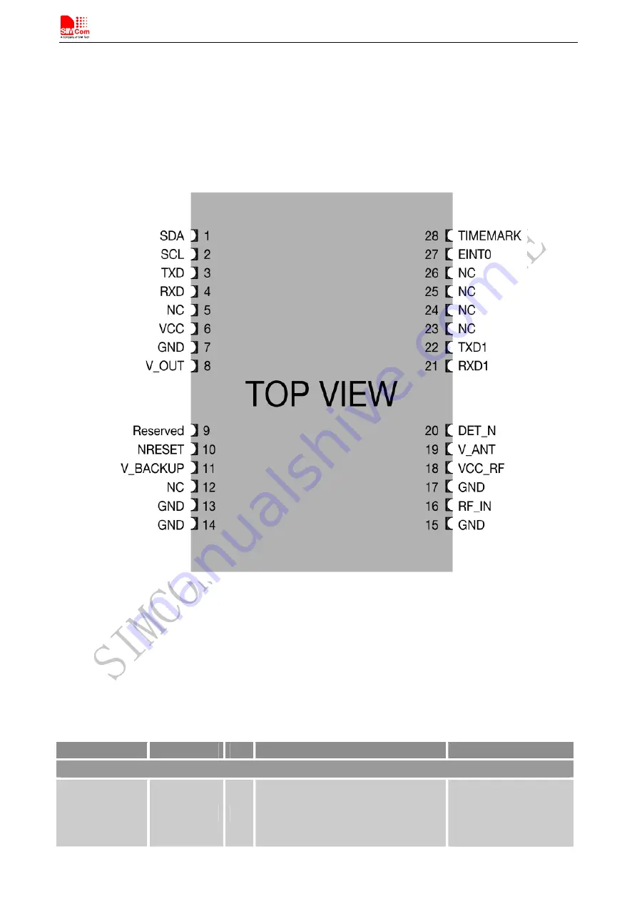
Figure 2: SIM68R pin out diagram (Top view)
3.2
Pin Description
Table 3: Pin description
Pin name
Pin number
I/O
Description
Comment
Power supply
VCC
6
I
Main power input, which will be used
to power the baseband and RF section
internally.
Provide clean and stable
power source to this pin.
Add a 4.7uF capacitor to
this pin for decoupling.
SIM68R_Hardware Design_V1.02
12
2013-01-22