background image

PerformaxIQEasyEx_UM_9752153510_NL_D_GB_FR_V1_4

79

GB

Colour:

Connection:

Number:

Brown

+ 24 V

1

White

A

2

Blue

0 V

3

Black

B

4

Yellow/green or grey

Earth

5

For an EX-bar with cable without protective hose:

When needed: cut the cable to the desired length, strip 
the cable according to figure 5.2.8.7 and mount proper 
ferrules to the end of the wires.

Turn the gland in the Status Module and run the cable 
through the gland. Tighten the clamp ring of the bolt for 
good sealing and relief from straining.
Connect the cable according to the table below, place 
the cover and screw tightly.

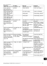
Image 5.8.2.11: Wiring connection Performax Easy EX (Speed) with Status Module

Summary of Contents for ION Performax IQ Easy Ex

Page 1: ...e antistatique 1180 II 2 GD Ex mb IIB T4 Gb Ex mb IIIB T135 C Db SIMCO Nederland B V Postbus 71 NL 7240 AB Lochem Telefoon 31 0 573 288333 Telefax 31 0 573 257319 E mail general simco ion nl Internet http www simco ion nl Traderegister Apeldoorn No 08046136 NL Gebruikershandleiding D Bedienungsanleitung GB User Manual 1 32 66 FR Mode d emploi 98 ...

Page 2: ...PERT mode for setting parameters or maintenance tasks 82 6 3 Calibrating the Performax IQ Easy Ex through the IQ Easy Platform 82 6 4 Operating modes expert 83 6 4 1 Operation Mode Manual 84 6 4 2 Operation mode CLFB Closed Loop FeedBack with IQ Easy sensor 85 6 5 Anti static bar Standby Active and Autorun setting 85 6 6 Anti static bar Information parameters expert mode 86 6 7 Switching the bar o...

Page 3: ...our entitlement under the guarantee The terms of the guarantee are set out in the Simco Ion Netherlands General Terms and Conditions of Sale Explanation of symbols Warning Indicates special information to prevent injury or significant damage to the product or the environment Attention Important information for making the most efficient use of the product and or for preventing damage to the product...

Page 4: ... conductors to the IQ Easy platform With the IQ platform the anti static bar can be controlled and read out centrally and remotely Using the IQ Easy platform the status of the bar can be logged making quality management easier The Performax IQ Easy Ex is optimally deployed between 100 and 300 mm away from the material at material speeds below 500 meters per minute and is available in effective len...

Page 5: ...ns from the anti static bar are exchanged with the charged material until the material is neutralized You can see via the status LED if the anti static bar is in operation and if it is overloaded In addition through the Manager IQ Easy divers parameters limit values and information concerning the functioning efficiency can be recorded and logged To learn more refer also to the user manual of the M...

Page 6: ...eed in such a way there is no possible mechanical damage The Performax IQ Easy Ex should be mounted at a distance of 100 to 300 mm The Performax IQ Easy Ex Speed should be mounted at a distance of 50 to 300 mm To ensure the safe operation the working temperature should be kept below 40ºC Electrical installation should be done only by a skilled electrical engineer and in accordance with all nationa...

Page 7: ...Standard Simco 5x0 34 mm2 M12 Male Female cable 62 5m 45m 15m Type power supply 100 240 V AC Manager IQ Easy 100 240 V AC Extension IQ Easy Input Remote on off 10 30 V DC nominal Ri 10k Activation time 30 ms Output Output voltage emitters Max 9 kV positive and negative Current per emitter to earth Max 50 µA High voltage OK HV OK Supply voltage 1 V max 50 mA Environment Usage Industrial indoor usag...

Page 8: ... IQ Easy Ex Speed 90 2790 mm In increments of 60 mm Dimensions exclusive Mounting brackets Tot length Eff length 250 mm with protective hose Tot length Eff length 180 mm without protective hose Width 30 mm Height 52 mm Weight 2 2 kg m Enclosure Aluminum PA6 PUR Universal Mounting brackets PA66 6 Image 4 1 1 Dimensions Performax IQ Easy Ex Speed ...

Page 9: ... prevent any electrical shock when touched Connect the ground terminal on the anti static bar to a grounded part of the machine with a wire of a minimum size of 4mm2 Use the Performax IQ Easy Ex Speed always in combination with the Ex Status Module and IQ Easy Manager and or Extension IQ Easy The anti static bar is powered and controlled via the IQ Easy Platform See the list of spare parts and acc...
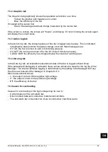
Page 10: ...re the static electricity problem occurs Place with an optimal distance from the material that should be neutralized o 100 300 mm Performax IQ Easy Ex o 50 300 mm Performax IQ Easy Ex Speed With the emitters in the direction of the material to be neutralized Ensure that no material can come between the emitters and the material to be neutralized Attach the cable properly into the machine to preven...

Page 11: ...B 5 4 Mounting brackets The anti static bars are provided with at least two mounting brackets with which the anti static bars can be attached in many different ways Image 5 4 1 Mounting brackets Performax IQ Easy Ex Speed dimensions and mounting options ...

Page 12: ... the same direction Use suitable M5 fixing materials 3 Slide the brackets 4 on the anti static bar 5 Place the anti static bar with brackets on the mounting feet and push the brackets 4 in the opposite direction of the three triangles Lock the bracket 4 by tightening at least one of the two set screws 7 a screw is on both sides Position the ionization points above the material to be neutralized Se...

Page 13: ...ypes are available 5 8 Connecting the Anti static bar Warning Observe the warnings at the beginning of this chapter The Ex Status Module must be mounted outside the Ex zone Use the Performax IQ Easy Ex Speed always in combination with an Ex Status Module Never connect the Performax IQ Easy Ex Speed directly to the power supply this is because the Ex Status Module contains the required fuse 0 5 AT ...
Page 14: ...ide Push the protective hose into the fitting of the ionization bar until the yellow seal is no longer visible see image 5 8 2 5 Insert the grey clip into the fitting with the slot facing the outside so it can be removed with a screw driver if required see image 5 8 2 6 Push a yellow seal on the protective hose on the status module side When needed strip the cable according picture 5 8 2 7 mount p...

Page 15: ...V1_4 77 GB Image 5 8 2 3 Length protective hose Image 5 8 2 4 Yellow seal on protective hose Image 5 8 2 5 Protective hose in fitting Image 5 8 2 6 Clip in fitting Image 5 8 2 7 Strip the cable Image 5 8 2 8 Mounting of fitting on Status Module ...
Page 16: ...ing the outside 2 so it can be removed with a screw driver if required Then replace the cover and fasten with the screws Colour Connection Number Brown 24 V 1 White A 2 Blue 0 V 3 Black B 4 Yellow green or grey Earth 5 Image 5 8 2 10 Fixing a protective hose to the fitting 1 2 Connect the cable according to the table below Image 5 8 2 9 Connection wiring Performax Easy EX Speed with the Status Mod...

Page 17: ...le to the desired length strip the cable according to figure 5 2 8 7 and mount proper ferrules to the end of the wires Turn the gland in the Status Module and run the cable through the gland Tighten the clamp ring of the bolt for good sealing and relief from straining Connect the cable according to the table below place the cover and screw tightly Image 5 8 2 11 Wiring connection Performax Easy EX...
Page 18: ...onnected during operation of the IQ Manager Easy Hence it doesn t need to be switched off Image 5 8 3 2 Wiring connectors brown blue GND yellow green or grey brown black white white yellow green or grey black blue Ex Status Module cable side view Female connector M12 Manager Extension IQ Easy cable side view Male connector M12 2 white 1 brown 5 yellow green or grey 3 blue 4 black 2 white 3 blue 5 ...

Page 19: ...param appears on the info screen from the bar on the Manager or when the bar is not reqognized the Manager must be updated with the latest software Download the latest software version via www simco ion co uk software and follow the Upgrade instructions as described in the Manager manual When the M12 connection cable connects the anti static bar and the IQ Easy platform communication will be estab...

Page 20: ...the password and confirm with or return directly to the system settings page of the Manager if no password is required Click on and go to the device to check or change the parameters by clicking on behind the parameter or desired action By clicking you will return to the main screen 6 3 Calibrating the Performax IQ Easy Ex through the IQ Easy Platform The anti static bar should be calibrated when ...

Page 21: ...ng on the application the static charge will be neutralized and a small residual charge will remain 2 Manual not currently available For test applications or very specific applications the ratio between positive and negative ions can be set manually This is done by entering a ratio number Usually an even number of positive and negative ions will be produced 0 fixed By entering a number other than ...

Page 22: ...Click on Operation mode Select the desired operation mode Auto tune Manual CLFB is currently unavailable 6 4 1 Operation Mode Manual Once Manual mode is selected go to the following page symbol near the parameter Balance Click Balance offset and specify the desired positive or negative ionization with a number from 100 to 100 Confirm the selection by clicking The ionization is now continued with t...

Page 23: ...m The anti static bar will then calculate using the average measurement values of the active enabled segments To disable a segment click Enabled segments Select the segments to be disabled Confirm selection with Go with the previous page symbol to the parameter Operation mode Select CLFB The sensor bar should now be connected to the Performax IQ Easy Ex bar The anti static bar will now use the ave...

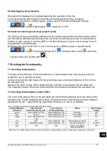
Page 24: ...Machine position Mounting distance Web width Web speed These are information parameters neither the bar or the Manager will use for calculations Select the information page with the parameters to be changed by n x parameter enter name of value confirm with 6 7 Switching the bar on off remotely through the remote on off input on the Manager or via fieldbus expert mode If desired the bar can be swit...

Page 25: ...azardous areas Connect the field strength meter with the grounding keep a minimum distance of 30 cm from the anti static bar Measure the static charge of the material before and after it has passed the anti static bar The measured charge must have minimized after the material has passed the anti static bar 7 2 Checking functionalities via the LED s The color of the status LED s of the anti static ...

Page 26: ...y or covered this value will drop Should the bar be set to standby this value will be 0 and the value between brackets will indicate the most recent value e g 0 98 Ionization current uA both the negative and the positive ionization current that the bar provides will be displayed here Balance offset 40 0 indicates the ratio of the ion output Depending on the selected Operation mode this value will ...

Page 27: ...V NOT OK the bar is turned off or the HV doesn t function properly CLEAN BAR the efficiency has dropped below the clean bar warning level 7 3 4 Data log tab In the Data log tab all available measurement data of the bar is logged at fixed times If the parameter Datalogging is activated these values will also be saved in the log file of the Manager The interval between logging is determined by the s...

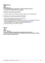
Page 28: ...smount the anti static bar as described in chapter 5 Remove the anti static bar from the Ex zone Clean the anti static bar with a suitable cleaning material e g Isopropylalcohol By very heavy contamination Veconova 10 can also be used www eco nova nl Let the anti static bar dry completely before putting back into use Mount the anti static as described in chapter 5 9 Faults Warning Disconnect the p...

Page 29: ...z Anti static bar over loaded Anti static bar contaminated Clean Anti static bar Anti static bar mounted too close to conductive machine parts Reposition the Anti static bar LED on anti static bar blinks red green 1Hz and Led on Ex Status Module blinks green 1Hz No poor ionization though High voltage on the emitters Anti static bar contaminated Clean Anti static bar Emitters are damaged Replace th...

Page 30: ...epaired For ordering replacement parts see the list of replacement parts By problems or questions contact Simco Ion or the local representative Simco Ion provides advice on sending items for repairs as below Follow the procedure by visiting www simco ion co uk repair Ensure the anti static bar is properly packed and be sure to clearly state the reason for return For dismounting the anti static bar...

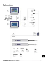
Page 31: ...PerformaxIQEasyEx_UM_9752153510_NL_D_GB_FR_V1_4 93 GB Replacement parts ...

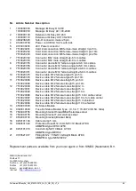
Page 32: ...emale straight 5 pin 5m 7519020366 Device cable M12 female straight 5 pin 10m 12 7519020390 Device cable M12 female male straight 2 m 7519020391 Device cable M12 female male straight 5 m 7519020392 Device cable M12 female male straight 10 m 7519020386 Device cable M12 female male straight 5 m for cable carrier 7519020387 Device cable M12 female male straight 10 m for cable carrier 7519020383 Devic...

Page 33: ...B T4 Gb Ex mb IIIB T135 C Db Notified Body EC type exam quality Baseefa 1180 Buxton UK EC Type Examination Certificate Baseefa17ATEX0012X Used Harmonized Standards The product is assessed and confirmed to comply to the Essential Health and Safety Requirements from the ATEX directive 2014 34 EU EN60079 0 2012 A11 2013 EN60079 18 2015 Other Standards and Specifications used Electromagnetic Compatibi...

Reviews: