background image

MOON 310LP Phono Preamplifier


Internal Settings    (cont’d) 


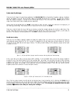
Capacitance Loading: 


There are three (3) different settings available for setting the capacitive load; 0pF, 100pF and 470pF which are represented by 
jumper sockets J6, J7 and J8 respectively for the left channel and jumper sockets J24, J25 and J26 for the right channel (refer 
figure 4 below). The factory default setting is 100pF, therefore jumpers will be found in sockets J7 & J25.   


Figure 4:  Left and right channel jumper banks for capacitance load adjustments at default settings


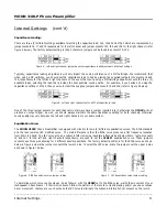
Typically, capacitance loading adjustments will only impact the sonic performance of a MM cartridge. We recommend that 
when using a MC cartridge, you should set the capacitance load to 0pF by placing the supplied jumpers into sockets J6 and 
J24, respectively for the left and right channels. In the event that you’re using a MM cartridge experiment with the three (3) 
available loads, selecting the load that provides the best possible sound quality.  For example, if you decided on using the 
capacitance setting of 470pF, then you would insert the supplied jumpers into sockets J8 and J26 (refer to figure 5 below). 


Figure 5:  Left and right channels set to a 470pF capacitance load 


One of the three jumper sockets for each channel must always have a jumper inserted into it, otherwise the 310LP will not 
produce an output signal. As well, you should always maintain the same capacitance setting for both channels, otherwise 
sound quality may vary between the left and right channels of your audio system. 
 
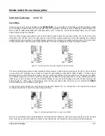
Equalization Curve: 


The MOON 310LP Phono Preamplifier is equipped with circuitry for two (2) different equalization curves; The RIAA standard 
and the less common IEC modified curve.  The main difference is that the RIAA curve produces a flat frequency response 
from 20Hz to 20kHz; The IEC curve acts as a subsonic filter removing inaudible infrasonic bass below 20Hz.  Jumper sockets 
J5 and J21, for the left and right channels respectively, are used to set the 310LP’s equalization curve. These jumpers 
sockets have three pins allowing for 2 different possible positions. The factory default position is for the RIAA curve as shown 
below in figure 6 where the jumper connects the lower 2 pins. To select the IEC curve, place the jumper over the upper 2 pins 
as shown in figure 7 below. 


      Figure 6:  RIAA Equalization curve jumper setting 


           Figure 7:  IEC Equalization curve jumper setting 


To determine which curve you should use, do as follows:  with the 310LP set to the RIAA curve, watch the movement of your 
loudspeaker’s bass drivers – if their motion doesn’t follow the pattern of the record currently playing and/or you see excessive 
driver movement, chances are you should use the IEC curve to eliminate the subsonic information not present on the record. 

____________________________________________________________________________________ 


Internal Settings   


       9

Summary of Contents for MOON 310LP

Page 1: ...Owner s Manual MOON Series 310 LP Phono Preamplifier...

Page 2: ...onvenience receptacles and the point where they exit from the apparatus Unplug mains cord during transportation 11 Only use attachments and accessories specified by the manufacturer 12 Use only with t...

Page 3: ...nd rear panel serial number label will indicate the correct voltage Use of any other voltage will likely damage the unit and void the warranty 3 AC extension cords are NOT recommended for use with thi...

Page 4: ...Board Layout 7 Internal Settings 8 Using the 310LP with an External Power Supply 11 Rear Panel Connections 12 Operating the 310LP 13 Specifications 14 www simaudio com Simaudio Ltd 1345 Newton Road B...

Page 5: ...otion of music and build our products with the goal of faithfully capturing these elusive qualities The information contained in this manual is subject to change without notice The most current versio...

Page 6: ...vibrations A symmetrical circuit design with accurate matching of the very finest high quality electronic components Designed to be powered up at all times for optimal performance Low operating tempe...

Page 7: ...310LP Circuit Board layout Available Settings A Resistance loading jumper bank B Capacitance loading jumper bank C Equalization curve jumper bank D Gain level jumper bank ____________________________...

Page 8: ...ly for the left channel and jumper sockets J27 J28 J29 J30 and J31 for the right channel refer figure 2 below The factory default setting is 47k therefore jumpers will be found in sockets J13 J31 Figu...

Page 9: ...output signal As well you should always maintain the same capacitance setting for both channels otherwise sound quality may vary between the left and right channels of your audio system Equalization C...

Page 10: ...bank are mounted to the left In the event that you are using a MC cartridge you will need to change the gain setting to either 54dB 60dB or 66dB The basic rule to determine gain for a MC cartridge is...

Page 11: ...OON 310LP in conjunction with the MOON 320S you will need to move these 2 jumpers into sockets STR1 and STR3 positions A in figure 10 For further details please refer to your MOON 320S owner s manual...

Page 12: ...nce of your system Finally on the right side the IEC receptacle labeled AC Power for the included AC power cord Directly above the IEC receptacle is a 4 pin XLR connector labeled DC Power this is for...

Page 13: ...performance from your audio system we strongly recommend that the detachable power cord not come into physical contact with any of the interconnect cables running to and from your 310LP In the event t...

Page 14: ...0dBr Signal to noise Ratio full scale 40dB gain 114dBr with 320S Power Supply Signal to noise Ratio full scale 66dB gain 88dBr Signal to noise Ratio full scale 66dB gain 92dBr with 320S Power Supply M...

Reviews: