background image

MOON 310LP Phono Preamplifier


Introduction 


Your MOON 310LP Phono Preamplifier incorporates many significant design features to achieve its “world class” level of 
performance.  This is an abbreviated list of the more important features:    


Isolated power supply on a separate circuit board using a toroidal transformer with 2 stages of voltage regulation. 


An extremely short signal path for a faster transient response.    


End-user adjustments for capacitance loading, resistance loading and gain level to extract exceptional performance 
from virtually all high quality phono cartridges. 


End-user adjustments to alternate between the RIAA and IEC equalization curves. 


Single-ended RCA and Balanced XLR output connectors. 


Optional external power supply


Power supply voltage regulation includes i

2

DCf (Independent Inductive DC Filtering) derived from the Evolution Series for 

increased dynamic range. 


Four-layer PCB tracings with dedicated ground and power planes using pure copper for low impedance characteristics. 
The advantages are better circuit layouts resulting in much shorter signal paths and a vastly improved signal-to-noise ratio. 


Rigid chassis construction to minimize the effects of external vibrations.     


symmetrical circuit design with accurate matching of the very finest high quality electronic components.  


Designed to be powered up at all times for optimal performance.  


Low operating temperature for a longer than normal life expectancy.    


Installation & Placement 


The  MOON 310LP requires reasonable ventilation to maintain an optimum and consistent operating temperature.  As a 
result, it should be placed in a location with empty space around it for proper heat dissipation. As well, it should be placed on 
a solid level surface. You should avoid placing it near a heat source or inside a closed cabinet that is not well ventilated as this 
could compromise this component’s performance and reliability. 

You should never place another component directly on top of 

this phono preamplifier. 

 
The 310LP is more sensitive than most other types of audio components to EMI (electro-magnetic interference) from power 
supplies and motors. Consequently, it should be placed at a minimum distance of 18 inches from power supplies, turntables, 
tape decks, AC line filters, etc.


IMPORTANT:   A turntable with a functional cartridge MUST be connected to the MOON 310LP Phono 

Preamplifier prior to connecting the AC power cord, otherwise you may damage your 
amplifier and/or loudspeakers. 


____________________________________________________________________________________ 


Introduction  /  Installation & Placement        


       6

Summary of Contents for MOON 310LP

Page 1: ...Owner s Manual MOON Series 310 LP Phono Preamplifier...

Page 2: ...onvenience receptacles and the point where they exit from the apparatus Unplug mains cord during transportation 11 Only use attachments and accessories specified by the manufacturer 12 Use only with t...

Page 3: ...nd rear panel serial number label will indicate the correct voltage Use of any other voltage will likely damage the unit and void the warranty 3 AC extension cords are NOT recommended for use with thi...

Page 4: ...Board Layout 7 Internal Settings 8 Using the 310LP with an External Power Supply 11 Rear Panel Connections 12 Operating the 310LP 13 Specifications 14 www simaudio com Simaudio Ltd 1345 Newton Road B...

Page 5: ...otion of music and build our products with the goal of faithfully capturing these elusive qualities The information contained in this manual is subject to change without notice The most current versio...

Page 6: ...vibrations A symmetrical circuit design with accurate matching of the very finest high quality electronic components Designed to be powered up at all times for optimal performance Low operating tempe...

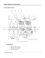
Page 7: ...310LP Circuit Board layout Available Settings A Resistance loading jumper bank B Capacitance loading jumper bank C Equalization curve jumper bank D Gain level jumper bank ____________________________...

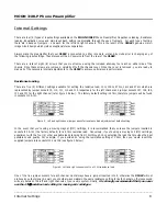
Page 8: ...ly for the left channel and jumper sockets J27 J28 J29 J30 and J31 for the right channel refer figure 2 below The factory default setting is 47k therefore jumpers will be found in sockets J13 J31 Figu...

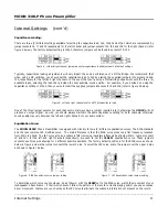
Page 9: ...output signal As well you should always maintain the same capacitance setting for both channels otherwise sound quality may vary between the left and right channels of your audio system Equalization C...

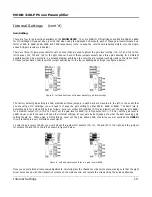
Page 10: ...bank are mounted to the left In the event that you are using a MC cartridge you will need to change the gain setting to either 54dB 60dB or 66dB The basic rule to determine gain for a MC cartridge is...

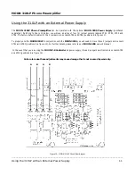
Page 11: ...OON 310LP in conjunction with the MOON 320S you will need to move these 2 jumpers into sockets STR1 and STR3 positions A in figure 10 For further details please refer to your MOON 320S owner s manual...

Page 12: ...nce of your system Finally on the right side the IEC receptacle labeled AC Power for the included AC power cord Directly above the IEC receptacle is a 4 pin XLR connector labeled DC Power this is for...

Page 13: ...performance from your audio system we strongly recommend that the detachable power cord not come into physical contact with any of the interconnect cables running to and from your 310LP In the event t...

Page 14: ...0dBr Signal to noise Ratio full scale 40dB gain 114dBr with 320S Power Supply Signal to noise Ratio full scale 66dB gain 88dBr Signal to noise Ratio full scale 66dB gain 92dBr with 320S Power Supply M...

Reviews: