background image

06

ıĵ

Screw holes for securing 
slim optical drive brace


ϛȁġġġМ

ᚬ໠ᐠ٘ήПĵᗻᖳ๛஠ᖡ࠮ӎᆅᐠЛ࢜ڥή

ENGLISH

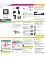
Loosen four screws located on the bottom side of the chassis to remove the slim optical drive bracket

DEUTSCH

Lösen Sie die 4 Schrauben an der Unterseite des Gehäuses um den optischen Slim Käfig herausnehmen zu können.

ESPAÑOL

Afloje dos tornillos que se encuentran en la parte inferior del chasis para quitar el soporte de la unidad óptica slim

Desserrez les 4 vis situées dessous le boîtier pour retirer le casier du lecteur optique slim.

FRANÇAIS

ITALIANO

Svitare 4 viti situate sul fondo del chassis per rimuovere il supporto dell’unità ottica sottile

ࠪࡖ࡯ࠪᐩㇱߩࡀࠫ

4

ᧄࠍᄖߒߡޔ⭯ဳశቇ࠼࡜ࠗࡉࡉ࡜ࠤ࠶࠻ࠍขࠅᄖߒ߹ߔޕ

Р ġ ҏ ġ ᇭ

ıĶ

Ĵ

ij

IJ

Secure motherboard onto the chassis with corresponding screws.  If the motherboard has either "S" or "R" 
type mounting holes, please install the included screw holder from the accessories bag

ENGLISH

Befestigen Sie das Motherboard auf den zugehörigen Halterungen mit Schrauben. Sollten Sie ein Motherboard 
mit "S" oder "R" Bauart benutzen, so installieren Sie bitte die zusätzlichen Motherboard Abstandshalter aus dem 
Zubehörpaket.

DEUTSCH

Fixez la carte mère dans le boîtier avec les vis adéquates. Si la carte mère possède des trous de montage de 
type “S” ou “R”, veuillez installer les supports de vis inclus dans le sachet d’accessoires.

FRANÇAIS

Sujete la placa base sobre el chasis con los tornillos correspondientes. Si la placa base tiene agujeros de tipo 
“S” o “R”, inserte también el portatornillos que se encuentra en la caja de los accesorios

ESPAÑOL

Fissare la scheda madre sul chassis con le viti correspondenti. Se la scheda madre ha dei fori di montaggio di tipo 
“S” o “R” utilizzare gli appositi tasselli per le viti, che si trovano nella scatola degli accessori.

ITALIANO

஠кᐠݖᚇھܻᐠ٘ۻ৴ࣺᄇᔖޟЌΰȂषԤкᐠݖΰԤŔܖ࢐œЌȂ፜ѪѴԊ၆ႭӇѓϛޟᖳ๛৴Սۻ৴Ȅ

ϛȁġġġМ

ࡑࠩ࡯ࡏ࡯࠼ࠍࠪࡖ࡯ࠪߦኻᔕߒߚࡀࠫߢ࿕ቯߒ߹ߔޕࡑࠩ࡯ࡏ࡯࠼ߦ ̌

S

̍߹ߚߪ̌

R

̍࠲ࠗࡊߩขࠅઃ

ߌⓣ߇޽ࠆ႐วߪޔࠕࠢ࠮ࠨ࡝ࡄ࠶ࠢౝߩࡀࠫࡎ࡞࠳࡯ࠍขࠅઃߌߡߊߛߐ޿ޕ

Р ġ ҏ ġ ᇭ

Summary of Contents for Milo series ML02

Page 1: ......

Page 2: ...k plus silver SST ML02B R black w out LCD panel SST ML02B MXR black with LCD panel Micro ATX Mini ITX DTX External Slim optical slot x 1 internal 3 5 x 1 or 2 5 x 1 vibration dampening Top Oversized v...

Page 3: ...Silm type optical device HDD LED Door Power LED Power SW LCD IR ML02MX 50 x 15mm fan slot optional 50 x 15mm fan slot optional 50 x 15mm fan Riser card brace 120W DC to DC board I O IEEE 1394 x 1 USB...

Page 4: ...Card TYPE I Compact Flash Card TYPE II Compact Flash Ultra Card TYPE I Compact Flash Ultra I Card TYPE I Compact Flash Extreme III Card Micro Drive Card Smart Media Card Secure Digital Card Secure Di...

Page 5: ...DEUTSCH Desserrez les 3 vis de l arri re du bo tier FRAN AIS Afloje tres tornillos de la parte trasera de la caja ESPA OL Svitare tre viti dalla parte posteriore del chassis ITALIANO 3 Loosen two scr...

Page 6: ...ase install the included screw holder from the accessories bag ENGLISH Befestigen Sie das Motherboard auf den zugeh rigen Halterungen mit Schrauben Sollten Sie ein Motherboard mit S oder R Bauart benu...

Page 7: ...PCI PCI PCI PCI A 2 5 B 3 5 Install hard drive can use either 2 5 or 3 5 size into the case and secure it with screws from the bottom of the chassis ENGLISH Installieren Sie die Festplatte in das Geh...

Page 8: ...peuvent tre ins r s dans le premier ou le deuxi me emplacement Tournez le casier 180 degr s et ensuite utilisez 2 vis pour les fixer au casier Puis utilisez 2 vis pour fixer le casier FRAN AIS PCIE 1...

Page 9: ...oisi me ou quatri me emplacement celui qui est disponible de la carte m re Puis installez la carte d extension PCI dans l adaptateur et fixez la avec FRAN AIS Inserte la tarjeta hija de la tarjeta ris...

Page 10: ...e la nidad ptica slim con el soporte instalado en el chasis y atornille desde la parte inferior Inserire nel chassis l unit ottica sottile con il suo supporto installato e fissare con le viti avvitand...

Page 11: ...ack and red The black wire should have the connector labeled GND Refer to your motherboard manual and connect the two wire leads to power switch or power button on the motherboard s front panel pin he...

Page 12: ...specifically for SilverStone s MoDT enclosures the NT07 is a perfect solution for low noise CPU cooling in ML02 system compatible with Socket 478 479 Intel mobile CPUs utilizing Socket 478 bracket Si...

Page 13: ...13 W D Warranty Information T W...

Page 14: ......

Reviews: