


User Guide (Version 2.2) of the
SiRad Simple® Evaluation Kit
- 7 -
2
Installation
2.1 Hardware Setup
2.1.1 Understanding the External Header (J1)
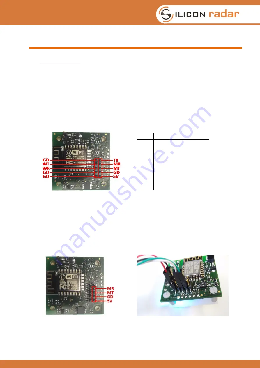
The external header in Figure 2 is used to connect to the sensor board in different operating
modes. In UART mode, the external header is used to connect a UART cable with RX/TX lines and
power supply to the sensor board. The data connection setup via UART is explained in Section
2.1.2. In WiFi mode, the external header is used to connect the WiFi module to the microcontroller
on the board. The wireless data connection setup via WiFi is explained in Section 2.1.3. In
programming mode, the external header is used to program either the WiFi module or the
microcontroller, please see Section 5. The external header can also be used to trigger
measurements manually via the external trigger line (TR), also see Section 3.2.3.1.
Pin
Description
5V
+5V
GD
GND
MT
microcontroller TX
*
MR
microcontroller RX
*
TR
external trigger line
*
WT
WiFi TX
*
WR
WiFi RX
*
* 3.3V tolerant only!
Figure 2: External header (J1) pinout
2.1.2 Data Connection via UART Cable (UART Mode)
If you want to connect to the sensor via WiFi instead of UART, please directly continue with
Section 2.1.3. The UART interface pins of the sensor board are shown in Figure 3 (left). You can
use the UART interface to connect the sensor board to a PC or in a target application with a serial
interface. Figure 3 (right) shows the sensor board with an FTDI cable attached to the external
header (J1), which provides a virtual serial port via USB to a PC.
Make sure to use a cable with
3.3V TTL (TX/RX) levels!
Figure 3: UART pinout on J1 (left) and UART to USB connection via FTDI cable at J1 (right)
The FTDI cable’s VCC is connected to +5V, the cable’s GND to any GD pin (there are four), the
cable’s RX to the TX line of the microcontroller (MT) and the cable’s TX to the RX line of the
microcontroller (MR).