Silicon Radar SiRad Easy Manual Download Page 11


- 11 - 

Evaluation Kit 

SiRad Easy® r4, SiRad Easy® & SiRad Simple® 

User Guide 

Version 2.5 

19-Nov-2021


4.1.2


Wireless Data Connection 

 
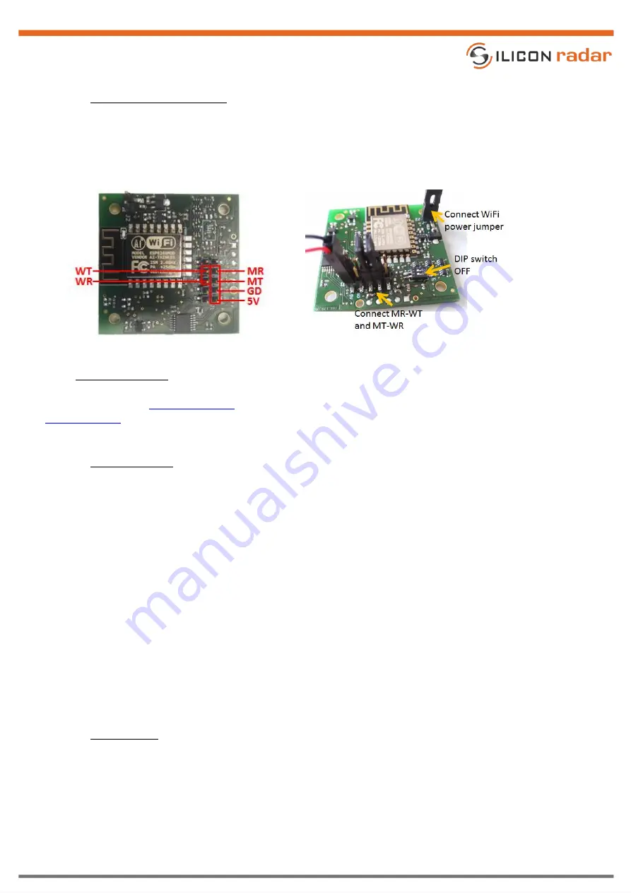
The WiFi interface pins of the sensor board are shown in Figure 15 (left). To run the sensor in WiFi mode, use the 
three jumpers delivered with the sensor and close the power jumper (J2) for the WiFi module (switched on) and 
connect two jumpers between MT/WR and MR/WT on the external header (J1). Apply +5V to the 5V pin and GND 
to the any GD pin (there are four). 


Figure 15 

WiFi pinout on J1 (left) and WiFi mode configuration (right) 


4.2


Firmware Update 

 
Please  also  see  the 

Firmware  Update

  Wiki  page  for  detailed  information  about  firmware  updates  and  the 

Download  Area

  to  download  the  stm32flash  tool  for  flashing  the  firmware  or  esptool  for  updating  the  WiFi 

firmware. 
 

4.2.1


Microcontroller 

 
To  update  or  change  the  microcontroller  firmware,  the  board  has  to  be  set  in  bootloader  mode,  as  shown  in 
Figure 16. This is done by switching the DIP switch MP to the ON position. Then connect the module to the PC via 
a Serial/USB (FTDI) cable or Serial/USB adapter using the external header (J1). Please read Section 4.1 about the 
external header connection. Connect line TX to MR (microcontroller RX) and line RX to MT (microcontroller TX).  
 

Make sure to use a cable with 3.3V TTL levels! 

 
Download the stm32flash tool. Copy the desired firmware into a folder together with the stm32flash tool. Edit the 
batch  file  stm32flash.bat  and  replace  the  COM  port  with  the  COM  port  of  your  Serial/USB  (FTDI)  cable  or 
Serial/USB adapter and the firmware name with the desired firmware, for example: 
 

stm32flash.exe -b 115200 -w <date>_SiRad_Simple_L8_<version>.bin -v -g 0x0 COMx 

 
The baud rate for flashing the firmware needs to be 115200 baud.  Run the batch file and the microcontroller gets 
programmed.  After  about  30  seconds  the  programming  is  finished.  Switch  the  DIP  switch  MP  back  to  the  OFF 
position and do a power cycle to reset the module. 
 

4.2.2


WiFi Module 

 
Connect the sensor using a Serial/USB (FTDI) cable or Serial/USB adapter as shown in Figure 17 using the external 
header (J1). Please read Section 4.1 about the external header connection. Switch the DIP switch WP to the ON 
position. Then connect cable TX to WR (WiFi RX) and cable RX to WT (WiFi TX).  
 

Make sure to use a cable with 3.3V TTL levels!  
 

Summary of Contents for SiRad Easy

Page 1: ...uide SiRad Easy Simple Version Product number Package Marking Page 2 5 1 of 14 Document Annex to VA U03 01 Anlage 8 Template Datenblatt RevE Date 19 May 2020 Rev D Silicon Radar GmbH Im Technologiepar...

Page 2: ...SiRad Easy r4 5 2 1 Changing the Radar Front End 5 2 2 UART Data Connection External Power External UART Header 5 2 3 PLL Control Connection External PLL Header 6 2 4 Data Connection External Power B...

Page 3: ...ed 7 Figure 8 External header J1 pinout 7 Figure 9 Hardware configuration for Serial USB connection 8 Figure 10 Hardware configuration for WiFi connection 8 Figure 11 WiFi module update configuration...

Page 4: ...a free graphical user interface WebGUI for user friendly parametrization of the baseband board and multiple visualization modes for radar data Due to the flexibility of the system it can be used to ch...

Page 5: ...anging the Radar Front End Figure 2 shows SiRad Easy r4 with a 122 GHz radar front end board mounted Follow the instructions below for changing the front end board Figure 2 122 GHz configuration with...

Page 6: ...he PLL Mx MUXOUT output line of uC reserved Da DATA line of the PLL Le LE line of the PLL Fs PLL FSK line of uC reserved 1 8V Figure 4 PLL control header pinout 2 4 Data Connection External Power Brea...

Page 7: ...controller board to exchange the front end board Assembly The radar front end can only be connected one way since the connector pins are different Slightly press it down and make sure no pins are bent...

Page 8: ...via the external header pins 5V and any of the four GD pins 3 2 2 Wireless Data Connection In WiFi mode the external header J1 is used to connect the WiFi module to the microcontroller on the board P...

Page 9: ...cable with 3 3V TTL levels Switch SW1 to the PROG position Figure 11 WiFi module update configuration Figure 12 WiFi module select switch SW1 Download esptool Copy the desired firmware into a folder...

Page 10: ...igger options in the Protocol Description Pin Description 5V 5V GD GND MT microcontroller TX MR microcontroller RX TR external trigger line WT WiFi TX WR WiFi RX 3 3V tolerant only Figure 13 External...

Page 11: ...I cable or Serial USB adapter using the external header J1 Please read Section 4 1 about the external header connection Connect line TX to MR microcontroller RX and line RX to MT microcontroller TX Ma...

Page 12: ...WiFi module gets programmed indicated by a flashing blue LED The programming is finished after about 40 seconds Switch the DIP switch WP back to the OFF position and connect a jumper between MT and WR...

Page 13: ...erial UART is available on the external header J1 lines MR and MT SER2 Serial USB is available on the USB port only on SiRad Easy You can connect to both SER1 and or SER2 using a terminal program such...

Page 14: ...l as any common law duties relating to accuracy or lack of negligence with respect to this material any Silicon Radar product and any product documentation Products sold by Silicon Radar are not suita...

Reviews: