


- 10 -
Evaluation Kit
SiRad Easy® r4, SiRad Easy® & SiRad Simple®
User Guide
Version 2.5
19-Nov-2021
4
Hardware Setup SiRad Simple®
4.1
Data Connection Mode - External Header (J1)
The external header in Figure 13 is used to connect to the sensor board in different operating modes. In UART
mode, the external header is used to connect a UART cable with RX/TX lines and power supply to the sensor
board. The data connection setup via UART is explained in Section 3.2.1. In WiFi mode, the external header is
used to connect the WiFi module to the microcontroller on the board. The wireless data connection setup via
WiFi is explained in Section 3.2.2. In programming mode, the external header is used to program either the WiFi
module or the microcontroller, please see Section 3.3. The external header can also be used to trigger
measurements manually via the external trigger line (TR), also see the section about trigger options in the
Pin
Description
5V
+5V
GD
GND
MT
microcontroller TX*
MR
microcontroller RX*
TR
external trigger line*
WT
WiFi TX*
WR
WiFi RX*
* 3.3V tolerant only!
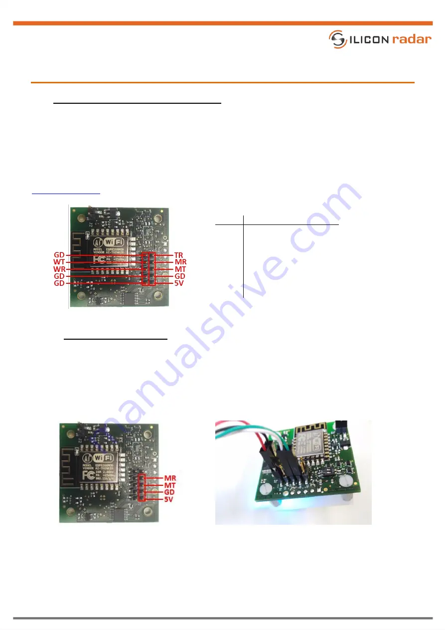
Figure 13
External header (J1) pinout
4.1.1
Serial/USB Data Connection
The UART interface pins of the sensor board are shown in Figure 14 (left). You can use the UART interface to
connect the sensor board to a PC or in a target application with a serial interface. Figure 14 (right) shows the
sensor board with a Serial/USB (FTDI) cable or Serial/USB adapter attached to the external header (J1), which
provides a virtual serial port via USB to a PC.
Make sure to use a cable with 3.3V TTL (TX/RX) levels!
Figure 14
UART pinout on J1 (left) and Serial/USB (FTDI) cable connection at J1 (right)
The Serial/USB (FTDI) cable’s VCC is connected to +5V, the cable’s GND to any GD pin (there are four), the cable’s
RX to the TX line of the microcontroller (MT) and the cable’s TX to the RX line of the microcontroller (MR).
Make sure that both DIP switches are in their OFF positions and the power jumper (J2) for the WiFi module is
open (switched off).