


- 12 -
Evaluation Kit
SiRad Easy® r4, SiRad Easy® & SiRad Simple®
User Guide
Version 2.5
19-Nov-2021
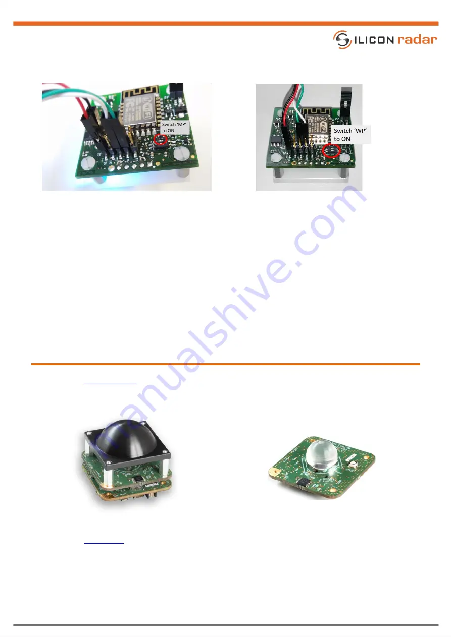
Now connect the power Jumper J2 to enable the supply voltage for the WiFi module.
Figure 16
Firmware update configuration
Figure 17
WiFi module update configuration
Download esptool. Copy the desired firmware into a folder together with esptool. Edit the batch file esptool.bat
and replace the COM port with the COM port of your Serial/USB (FTDI) cable or Serial/USB adapter and the
firmware name with the desired firmware, for example:
esptool -bz 1M -cp COMx -cf websocket_mini.ino.generic.bin
The baud rate for flashing the firmware needs to be 1 Mbaud. Run the batch file and the WiFi module gets
programmed, indicated by a flashing blue LED. The programming is finished after about 40 seconds. Switch the
DIP switch WP back to the OFF position and connect a jumper between MT and WR and MR and WT on the
external header (J1).
5
Mounting a Lens (Optional)
Please see the
data sheet for mounting our standard black lens for the 122 GHz transceivers and
further information. The Collimator Lens is hardware compatible with SiRad Easy® r4, SiRad Easy® and
SiRad Simple® evaluation kits.
Figure 18
Standard black lens
Figure 19
Acrylic lens
data sheet for mounting the small lens for the 122 GHz transceiver TRA
ˍ
120
ˍ
002 and
wideband 120 GHz transceivers TRA
ˍ
120
ˍ
031 / TRA
ˍ
120
ˍ
045 and further information. The Acrylic Lens is
hardware compatible with our 5mm x 5 mm packaged transceivers, independently of the evaluation kit.