background image

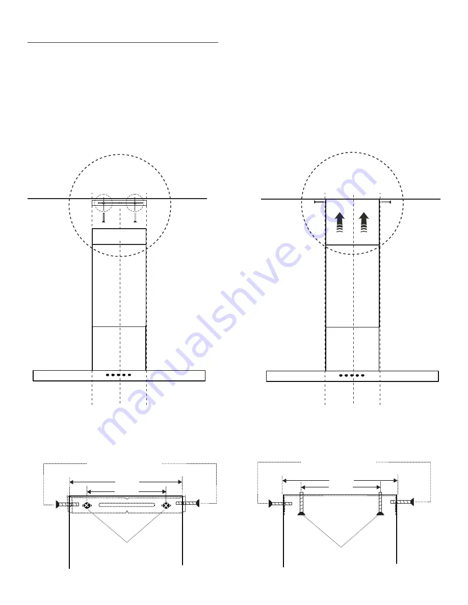
Locate the mounting bracket and center it on the wall just below the ceiling (Option A) 
or on the ceiling with the hooks facing downward (Option B) using 2 screws (see Fig. 
10.) Once the bracket has been mounted on the wall or ceiling, raise the extension fl ue 
toward the ceiling and line up the holes in the fl ue with the holes in the mounting bracket. 
Secure the extension fl ue by fastening it with 2 screws on each side (see Fig. 11.) Final 
install see Figs. 12 and 13.

5) MOUNTING BRACKET INSTALL

INSTALLATION INSTRUCTIONS

7

CEILING

CEILING

FIG. 10

FIG. 11

Raise 
extension 
flue toward
ceiling and
align the holes
then secure it
in place with 2 
screws on each 
side.

Fix the
mounting 
bracket to 
the wall or 
ceiling using 
2 screws.

1.

 Mount these screws to the wall

    to secure the mounting
    bracket

2.

 Align holes and secure 

    flue to the bracket with 2  
    screws on each side

FIG. 12

 - Bracket on wall (Option A)

12-1/2”

8-1/2”

1.

 Mount these screws to the 

    ceiling to secure the mounting
    bracket.

2.

 Align holes and secure 

    flue to the bracket with 2  
    screws on each side

FIG. 13

 - Bracket on ceiling (Option B)

12-1/2”

8-1/2”

E & G x 2

D

D

E & G x 2

E & G x 2

D

D

D

D

Summary of Contents for DWRH303GSST

Page 1: ...rules and operating instructions before first use of this product Veuillez lire attentivement les consignes de sécurité et les instructions d utilisation avant l utilisation initiale de ce produit Lea y observe todas las reglas de seguridad y las instrucciones de operación antes de usar esto producto por primera vez Model Modéle Modelo DWRH302SSST V2 05 12 DM ...

Page 2: ...Model Number Serial Number Date of Purchase Dealer PLEASE STAPLE YOUR SALES RECEIPT TO THE INSIDE FRONT COVER ...

Page 3: ...Seguridad Importantes Ubicar el Conducto Instalción Operación Reemplazar la Bombilla Limpieza y Mantenimiento Resolución de Problemas Garantía ENGLISH FRANÇAIS ESPAÑOL 1 Consignes importantes relatives à la sécurité Conduits Installation Fonctionnement Remplacement de l ampoule Nettoyage et entretien Dépannage Garantie 14 15 16 20 21 22 22 23 24 26 27 28 32 33 34 34 35 36 DWRH302SSST ...

Page 4: ...oths or tow els a violent steam explosion could result 4 Use an extinguisher ONLY if A You know you have a Class ABC extinguisher and you already know how to operate it B The fire is small and contained in the area where it started C The fire department has already been called D You can fight the fire with your back to an exit Based on Kitchen Fire Safety Tips published by NFPA CAUTION 1 To reduce...

Page 5: ...s M3 x 8mm Pan Head 2 D Mounting Screws M4 x 8mm Round Head 2 E Mounting Screws ST4 x 12mm Self Tapping 2 F Mounting Screws ST4 x 35mm Self Tapping 4 G Drywall Anchors Φ6 x 30mm Φ H 8 x 35mm 1 Installation Instructions Determine whether the hood will discharge vertically or horizontally For vertical or horizontal discharge run ductwork between the hood location and roof cap or wall cap A minimum 6...

Page 6: ... of the screw roughly half an inch out of the wall until after the range hood is mounted 2 MOUNTING THE RANGE HOOD ON THE WALL Before mounting the range hood on the wall please take out the filters and remove any plastic or styrofoam found inside the range hood see Fig 3 and Fig 4 Leave the filters out until Step 3 is finished FIG 4 PEEL OFF PLASTIC FROM THE FLUES FIG 2 26 min 34 max CEILING 9 13 ...

Page 7: ...ewdriver may be required to access the screws from inside the range hood Once the range hood is securely fastened the filters can be put back in At this point the range hood should match Fig 6 5 Please tighten the 2 screws from the inside FIG 5 26 min 34 max CEILING 9 13 1 2 FIG 6 LEVELING DEVICE When mounting hood on the wall the level can be adjusted by turning the two screws on the motor housin...

Page 8: ...range hood DO NOT SEPARATE THE EXTENSION FLUE Have one person hold the flue and the other person align the holes on the decorative flue with the holes on the range hood brackets Fasten the 2 screws on each side see Fig 9 6 Connect house power cable to range hood wiring Ground Wire GREEN Fire Wire BLACK Zero Line WHITE 1 FIG 8 Wiring diagram CEILING FIG 7 Blower Housing Exhaust tubing duct STEP 1 A...

Page 9: ...5 MOUNTING BRACKET INSTALL INSTALLATION INSTRUCTIONS 7 CEILING CEILING FIG 10 FIG 11 Raise extension flue toward ceiling and align the holes then secure it in place with 2 screws on each side Fix the mounting bracket to the wall or ceiling using 2 screws 1 Mount these screws to the wall to secure the mounting bracket 2 Align holes and secure flue to the bracket with 2 screws on each side FIG 12 Br...

Page 10: ...5 FINAL INSTALLATION IMAGE INSTALLATION INSTRUCTIONS 8 26 min 34 max CEILING 9 13 1 2 FIG 14 12 1 2 8 1 2 D D E G x 2 F H x 2 C C ...

Page 11: ... Press the icon a third time to turn the lights off Light After 100 hours the filter icon lights up and the user must re move the filter clean it and replace it in order to reset the icon Press and hold the power button for 3 seconds to reset after cleaning the filter Filter Silhouette Select range hoods include a convenient feature that allows the range hood to continue to run for an additional 5...

Page 12: ...Follow all cleaning with rinsing with clear water Wipe dry with a clean soft cloth to avoid water marks For discolorations or deposits that persist use a non scratching household cleanser or stainless steel polishing powder with a little water and a soft cloth For stubborn messes use a plastic scouring pad or soft bristle brush together with cleaning solution and water Rub lightly in direction of ...

Page 13: ... 1 Defective halogen bulb 1 Change the halogen bulb The hood is not venting out properly 1 The hood might be hanging to high from the cook top 2 The wind from the opened windows or opened doors in the surrounding area are affecting the ventilation of the hood 3 Blockage in the duct opening or duct work 4 The direction of duct opening is against the wind 5 Using the wrong size of ducting 1 Adjust t...

Page 14: ...e service location are not protected by this warranty and are the responsibility of the purchaser EXCLUSIONS Save as herein provided Danby there are no other warranties conditions representations or guarantees express or implied made or intended by Danby or its authorized distributors and all other warranties conditions representations or guarantees including any warranties conditions representati...

Page 15: ...ad Todas las partes de recambio pueden comprarse o encargarse especialmente en su taller de reparación autorizado Para solicitar servicio y o localizar el taller de servicio mas cercano llame a nuestro NÚMERO SIN CARGO Proporcione siempre la siguiente información al solicitar servicio o al ordenar partes Tipo de Producto Número de Modelo Descripción de la Parte HOTTE DE CUISINE Le numéro de modèle...

Reviews: