background image

IM_FULL_SL52FM_REV_A 

4

P R O F E S S I O N A L  S E R I E S

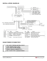
5 PIN MAIN POWER WIRE HARNESS: 

RED / WHITE WIRE –PARKING LIGHT RELAY INPUT —

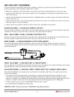
The RED/WHITE wire is the input to the flashing parking light relay. The connection of the RED/WHITE wire will  

determine the output polarity of the flashing parking light relay.  
If the vehicle you are working on has +12volt switched parking lights, you don’t need connect this wire. This wire is 

already connected to +12volt.
If the vehicle’s parking lights are ground switched, cut the RED/WHITE wire, connect the RED/WHITE wire to  

chassis ground.

WHITE WIRE — PARKING LIGHT RELAY OUTPUT 

(+12 V 10A OUTPUT) —

Connect the WHITE wire to the parking light wire coming from the headlight switch. Do not connect the WHITE wire to the 

dashboard lighting dimmer switch. (Damage to the dimmer will result). The limitation of the WHITE wire is 10 AMP max. 

Do not exceed this limit or damage to the alarm and parking relay will result.

BLACK WIRE — SYSTEM GROUND –

This is the main ground connection of the alarm module. Make this connection to a solid section of the vehicle frame. Do 

not connect this wire to any existing ground wires supplied by the factory wire loom, make the connection to the vehicle’s 

frame directly.

BROWN WIRE – (-) HORN OUTPUT – 

This wire is provides a ground output to be connected to the horn of the vehicle. A relay must be used if the horn requires 

a positive input. This output is only capable of 500 mA output

RED WIRE — SYSTEM POWER (+12V CONSTANT) —

The RED wire supplies power to the system. Connect this wire to a stable co12 volt source.

4 PIN ANTENNA, LED AND VALET SWITCH CONNECTOR:

The antenna should be mounted to the front windshield of the vehicle 

facing down. It should be clear of any metallic objects or tinting and 

as close to the center as possible. The Valet switch and LED are 

mounted within this unit and are connected with the ribbon cable.

Summary of Contents for SL-52FM

Page 1: ... unit is designed for professional installation only and must be installed by an authorized Silencer dealer Magnadyne Corporation 1111 W Victoria Street Compton CA 90220 800 340 3200 For Warranty information Please visit our website at www silencer com SL 52FM Two Way 3 Channel 915 MHz Extended Range Remote Start Keyless Entry System ...

Page 2: ...s or other components are located behind the panels that would otherwise be damaged Do not use conventional crimp lock bullet on any wiring Poor wiring i e taped joints will possibly introduce unreliability into the alarm system and may result in false alarms or incorrect operation We suggest soldering all connection points Install the wiring neatly under carpets or behind trim to prevent possible...

Page 3: ...P R O F E S S I O N A L S E R I E S INSTALLATION DIAGRAM MAIN POWER CONNECTOR RED WHITE PARKING LIGHT RELAY INPUT WHITE PARKING LIGHT OUTPUT BLACK MAIN SYSTEMS GROUND BROWN NEGATIVE HORN OUTPUT RED FUSED 12 VOLT BATTERY POWER ...

Page 4: ...ITE wire is 10 AMP max Do not exceed this limit or damage to the alarm and parking relay will result BLACK WIRE SYSTEM GROUND This is the main ground connection of the alarm module Make this connection to a solid section of the vehicle frame Do not connect this wire to any existing ground wires supplied by the factory wire loom make the connection to the vehicle s frame directly BROWN WIRE HORN OU...

Page 5: ... Failure to make this connection properly can result in personal injury and property damage In all installations it is the responsibility of the installing technician to test the remote start unit and assure that the vehicle cannot start via RF control in any gear selection other than park or neutral In both mechanical and electrical neutral start switch configurations the connection of the VIOLET...

Page 6: ...the ignition switch The ignition wire should receive 12 volts when the ignition key is in the ON or RUN and START or CRANK position When the ignition is turned OFF the ignition wire should receive 0 voltage If the PINK wire is not used cap the end of the wire BROWN WIRE ACCESSORY OUTPUT HEATER AC OUTPUT Connect the BROWN wire to the accessory wire in the vehicle that powers the climate control sys...

Page 7: ...OR LOCKING SYSTEM TYPICAL OF MERCEDES BENZ AND AUDI Locate the wire under the driver s kick panel Use the voltmeter connecting to ground verify that you have the correct wire with the doors unlocked the voltmeter will receive 12 volts Lock the doors and the voltmeter will read 0 volt Move the alligator clip to 12V and the voltmeter will receive 12 volts Cut this wire and make connections Be sure t...

Page 8: ...EP DOOR UNLOCK WIRE CONNECTION FOR POSITIVE SWITCHED DOOR LOCKS Cut Existing Unlock Wire X Lock Unlock OEM Door Master Lock Switch To All Other Door Lock Motors White Green Wire OEM Driver s Door Lock Motor 12V Existing Pos Lock Wire Existing Pos Unlock Wire 30 87a 87 86 85 12V 12V OEM Door Lock Relay 86 30 85 87 87a Green Wire Door Unlock Blue Wire Door Lock H2 13 22 Pin Plug From Alarm H9 3 Pin ...

Page 9: ...e newer vehicles use a third ignition wire which is required to start and keep the vehicle s engine running If this is the case wire an IGN 3 relay not supplied as shown below Do not connect any vehicle circuits together they are isolated for a reason Yellow Wire 87a Ignition 3 Wire From Ignition Key Switch 12 V Constant Fused 25A Capable 30 85 86 87 TRANSPONDER INTERFACING USING RELAY If the vehi...

Page 10: ...ctor H1 ORANGE WIRE 200MA GROUNDED OUTPUT WHEN ARMED This wire will become grounded when the alarm is armed The current capacity of this wire is 200mA This output can control starter disable when an intrusion is detected and the system is triggered The vehicles prevent from any unauthorized starting WHITE BLUE WIRE INSTANT START TURN OFF INPUT This wire activates and turns off the remote starter e...

Page 11: ...and unlock the driver s door only If press disarm or unlock button two times within 3 seconds the alarm will disarm and all doors will unlock Factory Security Disarm Signal Output This wire is designed to disarm a factory installed security system This wire sends a negative 1 seconds pulse upon a remote start and remote door unlocking Some factory systems must be disarmed to allow remote starting ...

Page 12: ...ges engine computers and automatic transmission computers IMPORTANT Do not test tachometer wires with a test light or logic probe The vehicle will be damaged How to find a tachometer wire with your multi meter 1 Set the ACV or AC voltage 12V or 20V is fine 2 Attach the probe of the meter to chassis ground 3 Start and run the vehicle 4 Probe the wire you suspect of being the tachometer wire with th...

Page 13: ...t be connected to hear the programming chirps Press Transmitter Button One Chirp LED one pulse Factory Default Setting Two Chirps LED two pulse Three Chirps LED three pulse Four Chirps LED four pulse 1 Pathway illumination feature off Parking lights turn on for 30 seconds upon disarm Parking lights turn on for 30 seconds upon disarm 10 sec upon arm 2 Brown wire Horn Brown White wire Dome light Gra...

Page 14: ...nition controlled door Unlocks Only Without ignition controlled door locks unlocks 3 0 8 second door lock unlock 3 5 second door lock Unlock 0 8 second Lock 0 35 second Unlock 0 8 sec dbl Lock 0 8 sec dbl Unlock Five Chirps 0 8 second Lock double 0 8 second Unlock Six Chirps Double 0 8 second Lock 0 8 second Unlock Seven Chirps Door lock with Comfort Feature Eight Chirps DBI Two step unlock DBI ON...

Page 15: ... Wait To Start Light 15 sec warm up Diesel Engine Wait To Start Light 20 sec warm up 3 20 minutes run time 30 minutes run time 10 minutes run time 5 minutes run time 4 Factory alarm disarm with channel 2 on Without this feature 5 Constant parking light output upon Remote Start Flashing parking light output upon Remote Start 6 Vehicle without Turbo The system Cannot Arm with the engine running Vehi...

Page 16: ... second 0 8 second 2 chirps 1 0 second 3 chirps 1 2 second 4 chirps 1 4 second 5 chirps 1 6 second 6 chirps 1 8 second 7 chirps 2 0 second 8 chirps 3 0 second 9 chirps 4 0 second 10 chirps 3 Low check level Hi check level 4 Start or Stop the system for TESTING ADJUSTMENT 5 Voltage check type Tachometer Check type Timer checking type Data Bus Interface Mode 6 THICK Pink Ignition 2 THICK Pink Start ...

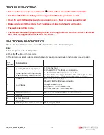
Page 17: ...ng light flash 3 times to confirming the system Start Feature C D Programming all returns to factory default setting SHUTDOWN DIAGNOSTICS The unit has the ability to report the cause of the last shutdown of the remote start system Enter 1 Turn the Ignition switch to ON position 2 Press the button on the transmitter 3 The LED will now report the last system shutdown by flashing for one minute in th...

Page 18: ...art system Enter 1 Turn the Ignition switch to ON position 2 Press the button on the transmitter 3 The LED will now report the last system shutdown by flashing for one minute in the following grouped patterns LED Flashes Shutdown Mode 1 Safety Shutdown input Hood 1 Close the hood 2 Check H2 13 White Black wire connection 2 Safety Shutdown input Brake or Neutral Safety Switch input fail 1 Check H2 ...

Page 19: ...t engage the test is complete b If the starter engages immediately step on the brake pedal to shut down the system recheck your VIOLET wire starter output wire connection The heavy gauge VIOLET wire must be connected to the ignition switch side of the Neutral Start Switch If the vehicle you are working on does not have an Electrical Neutral Safety Switch it will be necessary to reconfigure the Rem...

Page 20: ...g in gear WE ADVISE THAT YOU MAINTAIN THE FACTORY CIRCUIT WHENEVER POSSIBLE The following two circuits may be used only if the above circuit is not available NOTE When completing an installation using either of the following key in sensor circuits if the operator inserts the ignition key while the vehicle is running under the control of the Remote Start the vehicle will shut down This must be expl...

Page 21: ... 1 Locate the control wire that connects the driver s door pin switch to the key in sensor switch 2 Cut this wire and connect the ignition cylinder side to chassis ground 3 Locate the key in sensor switch wire that connects the chime module to the ignition cylinder 4 Cut this wire and connect the ignition cylinder side to the Remote Start Negative Safety Shut down wire Yellow using a 4003 series d...

Reviews: