IM_FULL_SL52FM_REV_A
10
P R O F E S S I O N A L S E R I E S
GM VATS KEY OVERRIDE:
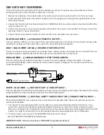
If the vehicle has the General Motor VATS system installed, you will need to by-pass the system while the vehicle is
operating under the control of the Remote Start Unit. To do this:
1. Measure the resistance of the resistor pellet on the ignition key then select a resistor within 5% of the key’s value.
2. Locate the pair of VATS wires in the vehicle, usually a pair of thin gauge wires running from the ignition switch to the
VATS control module.
3. Connect the YELLOW wire from Remote Start Unit to TERMINAL #85 of an external relay. Connect terminal #86 of the
relay to a fused +12 volt.
4. Cut (#1) wire (as shown), and connect the ignition switch side of the cut wire to terminal #87a of the relay. Connect the
other side of the (#1) wire to terminal #30.
5. Connect the previously selected resistor from terminal #87 to the second(#2) wire (as shown).
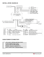
BLUE/BLACK WIRE – (-) 200 MA ACCESSORY 2 OUTPUT –
This wire provides a 200mA (-) ground output. This output will energize when the remote start is activated, go away while
the starter is cranking, and then come back on when the vehicle has started successfully.
GRAY / BLACK WIRE: 200 MA (-) SECOND STARTER OUTPUT.
This line can be used if a second starter line is needed. Some vehicles require a two-starter line to remote start. This wire
provides a negative output that will work the same way as the Violet starter line in connector H1.
ORANGE WIRE – (-) 200MA GROUNDED OUTPUT WHEN ARMED –
This wire will become grounded when the alarm is armed. The current capacity of this wire is 200mA. This output
can control starter disable, when an intrusion is detected and the system is triggered. The vehicles prevent from any
unauthorized starting.
WHITE / BLUE WIRE – (-) INSTANT START & TURN OFF INPUT –
This wire activates and turns off the remote starter each time it sees a momentary ground signal. Normally used for testing
during installation or when activating the module from an after-market system.
BLACK/WHITE WIRE – (-) NEUTRAL SAFETY SWITCH INPUT OR (-) ENABLE SWITCH INPUT –
When the BLACK/WHITE wire is grounded, the remote start unit is operable. When this wire is open from ground, the
remote start is disabled.
1. The optional “remote start toggle switch” can be added on to temporarily disable the Remote Start Device, it can
prevent the vehicle from being remote started accidentally. This feature is useful if the vehicle is being serviced or
stored in an enclosed area. To disable the remote start, move the optional remote start enable toggle switch to the OFF
position. To enable the remote start, move the optional remote start enable toggle switch to the ON position.
2. If needed, this wire can connect to the PARK/NEUTRAL switch in the vehicle.
(See the TESTING YOUR INSTALLATION GUIDE)
IMPORTANT NOTE: This wire must have a “GROUND” to operate remote start.
87
87a
85
30
86
IN4003 Diode
H2/15
: Orange wire
from control module
“Start”
“On”
Purple wire
X
Cut
Yellow
wire
White wire
“Acc”
“Off”
Starter
H1/1
VIOLET wire (Starter output)
form Heavy Gauge wire harness
Red wire to
Ignition Switch


