


MSK320R
Installation English
MSK320R · Date
30.01.2018 · Art.
No.
88942 · Mod.
status
42/18
24
4.4 Mounting the magnetic ring
Magnetic ring MR320
Slide magnetic ring MR320 onto the shaft and then tighten grub screw M6
to fix it to the shaft.
1. Ensure sliding fit between shaft and MR320.
2. Mount MR320 without force and without strain. Possible forces should
go to the metal flange. Avoid knocks on the magnetic ring.
3. Provide for a relief groove in the solid shaft (see
Fig. 8
).
Magnetic ring MRI01
Slide magnetic ring MRI01 onto the shaft and then tighten grub screw M4
to fix it to the shaft.
1. Ensure sliding fit between shaft and MRI01.
2. Mount MRI01 without force and without strain. Possible forces should
go to the metal flange. Avoid knocks on the magnetic ring.
3. Provide for a relief groove in the solid shaft (see
Fig. 8
).
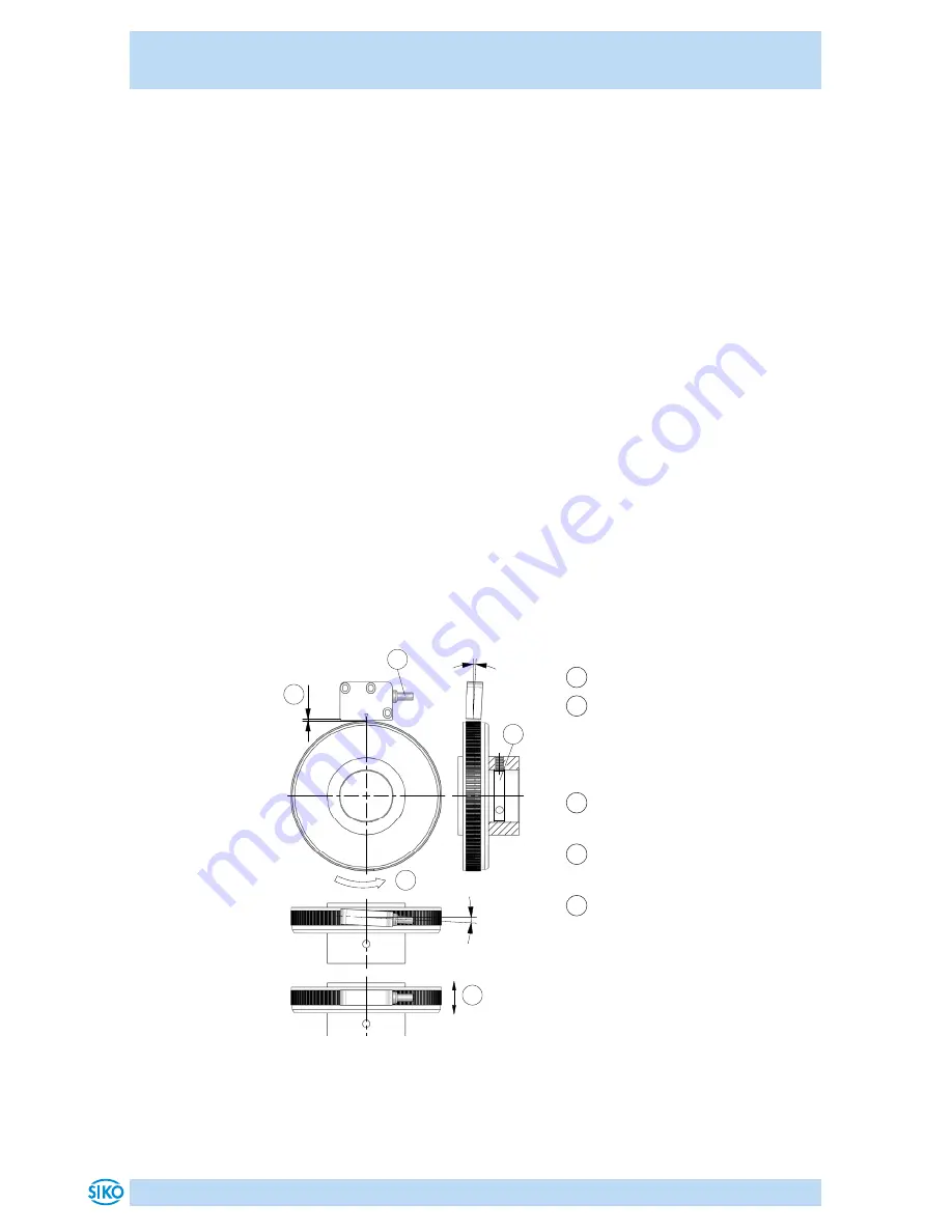
RADIAL application:
MSK320R design ZM with MRI01 or MR320:
1
Direction of outgoing cable
2
Admissible deviation of ring/
sensor
0.1 ... 2 mm reference point O
0.1 ... 1 mm reference point R
3
Direction of rotation of mag-
netic ring signal A before B
4
Undercut at the solid shaft for
tread plug is recommended
5
Admissable deviation middle
of tape/sensor
ref. O ±2 mm
Fig. 8: Definition of the counting direction with magnetic ring
and assemblage sensor/magnetic ring, gap measure, tolerances
1
2
3
5
4
<3°
<3°
Summary of Contents for MSK320R
Page 30: ...MSK320R 30...
Page 31: ...MSK320R 31...