July 2018
443580499131
Signify North America Corporation
200 Franklin Square Drive
Somerset, NJ 08873, USA
Phone: 855-486-2216
www.chloride-lighting.com
Signify Canada Ltd./Signify Canada Ltée.
281 Hillmount Road,
Markham, ON, Canada L6C 2S3
Phone: 800-668-9008
Self Diagnostic System Operation
–
Emergency Light or EXIT Sign Products
Normal Power Up Sequence
At power up the red and green LED indicators will alternately flash for one to two seconds. Next the product will execute
a “Power Up Quick Test” causing the green LED indicator to flash rapidly. If any faults are detected during the “Power Up
Quick Test”
these will be evident by a flashing red LED indicator. If the audible diagnostic option has been ordered, the
flashing red LED will be accompanied by a simultaneous beeping tone.
(Note: A continuous rapid alternating Red/Green
flash with rapid beeping tone indicates 277V applied to 120V input lead. TURN OFF POWER IMMEDIATELY!)
Emergency Operation
Emergency operation occurs when AC power fails. The product remains in emergency operation until AC power is
restored or battery capacity is depleted. During emergency operation both red and green LED indicators are disabled.
User Interface
Green LED indicator
•
Slow Flash/Continuous ON = AC power present; normal operating condition
•
Rapid Flash = product performing an automatic or manually initiated diagnostic test
Red LED indicator
•
Single Flash = battery fault
•
Two Flashes = lamp failure (light bar failure
–
EXIT signs)
•
Three Flashes = charger fault
•
Four Flashes = transfer fault
(If more than one fault condition is present simultaneously, the red LED will flash the indication pattern for each
fault independently then repeat the cycle.)
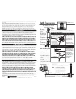
Pushbutton Test Switch
•
Long Press (longer than 0.5sec) transfers product to emergency operation during time the button is
pressed.
•
Short Press initiates self diagnostic activities as follows:
➢
One Press cancels diagnostic test presently running.
➢
Two Presses starts a one minute diagnostic test.
➢
Three Presses starts a 90 minute diagnostic test.
➢
Four Presses conducts a lamp load calibration (emergency light products only).
➢
Seven Presses initiates a system reset.
(Note: the microprocessor will allow up to seven, one minute diagnostic tests within the first 24 hours of
operation. Allow 24 hours of charging before performing any long duration testing.)
Buzzer
(optional)
–
Sounds in unison with the flashing red LED if a fault condition is present. Buzzer may be
silenced for up to 196 hours by a short press of either the test switch or the optional IR remote control device
“silence” button. Correcting fault condition will cancel fault n
otification. Lamp failure indication requires a
manually activated diagnostic test after lamp replacement to cancel notification.
IR Remote Control
(optional)- is a hand held device that allows remote activation of diagnostic testing and
silencing of the optional buzzer during fault conditions.