


CP6000/CP4000
Current Probe Instructions 9
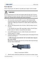
1.
Sensor Head
The core component to measure conductor current. The component contains a
precise semi-conductor that could be damaged by drastic change of environmental
temperature, external pressure and shock. Please be careful during measurement.
2.
Opening lever
The operating lever used to open the sensor head. Pull the lever to open the sensor
jaw, put in the cable under test, and push the lever to lock the sensor head to
measure the current.
3.
BNC Output Connector
The standard BNC port that can be connected to oscilloscope of any brand by a
standard BNC Coaxial Cable ( CK- 310 ).
4.
Overload Indicator LED
If / when the current under measured exceeds the limit current, the red LED will light
up and the buzzer will sound an alarm.
5.
Jaw on indicator
When the light is on, it means that the push rod is in the unlock state. Make sure that
the jaw is in the lock state during the measurement.
6.
Degaussing and Zero Setting Indicator
After pressing the degaussing zero button, the indicator light will be green, and after
degaussing, the indicator light will be off. If degaussing setting succeeds, the buzzer
will make two short beeps. If degaussing setting failed, the buzzer will make an
extension beep of about one second.
7.
Range LED Indicator
The green LED indicates the selected range.
8.
Degauss auto zero button
Frequent usage of the device will generate residual magnetic field. Please degauss
and zero set before measurement for better measurement precision. Press the
degaussing and auto zero button to trigger the process ( should be around 5s ) .
9.
Range selected button
Summary of Contents for CP4000 Series
Page 1: ...Current Probe Instructions ...
Page 2: ......


