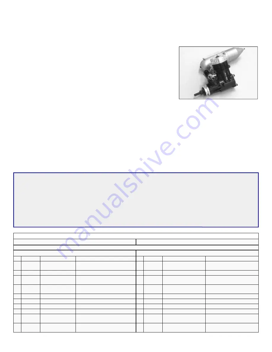
SIG Sealane Instruction Book Download Page 2

.


Engine Selection

 
Engine choices for the SEALANE are many. The SEALANE has been designed to produce excellent performance when using 
the recommended engine sizes. Do not use an engine larger than recommended.
 
2-stroke engines are a perfect choice to power your SEALANE. Any plain-bearing or 
bearing equipped .40 to .45 sport engine would be a good choice. For example, a 
great choice would be the Irvine .40 engine. Like all Irvine engines, the .40 is 
powerful, reliable, and quiet. Whatever engine you choose, take the time to carefully 
break it in according to the manufacturer’s instructions. A good running, reliable 
engine is a minimum requirement for the enjoyment of this or any R/C model aircraft. 
 
The SEALANE can also use a variety of 4-stroke engines. Any 4-stroke engine in 
the .40 - .50 displacement range should provide plenty of power. An important thing to 
remember is that typical 4-stroke engines have their throttle arms usually located 
differently than throttle arms on 2-stroke engines. If you want to power this model with 
a 4-stroke engine, you will likely have to install a new, relocated throttle cable tube. While this is not difficult, it is something to 
consider when choosing an engine.
 

Covering Material And Waterproofing

 
Your SEALANE has been designed to be completely covered with any of the popular plastic iron on covering materials on the 
market. These covering materials are waterproof and by carefully overlapping the seams approximately 3/32", your SEALANE 
will be almost waterproof. 
 
The only place on the model where water can enter the fuselage is at the joint where the wing attaches. Our prototype models 
were made with relatively tight fitting wings, with no additional sealing, and very little water was able to enter the fuselage.
 

Required Tools


A selection of glues:

A selection of hand tools, such as:

Sig Thin CA  

Sig Medium CA  

Sig thin CA applicator tips  

Sig Kwik-Shot Accelerator  

Sig Epoxy Glue (15 Minute 
Working Time) 

Regular size and miniature 
screwdrivers  

Regular size and miniature 
pliers  

Tweezers or small hemostats  

Hobby knife with several new 
#11 blades  

Sandpaper-assorted grits  

Sig Modelers “T” pins 

Drill Motor  

1/16” Drill Bit  

3/16” Drill Bit  

1/4” Drill Bit  

Covering Iron  

Wax Paper 

Fuel Proof Paint  

Small Paint Brush  

Razor saw or 
Hacksaw blade  

Pencil  

Small 90° Square  

Masking tape and 
Rubber bands 


COMPLETE KIT PARTS LIST

Laser Cut Parts

There are 13 Laser Cut Sheets included in this kit. Use the illustrations on the following pages to identify these parts.

Wooden Parts

Qty Assembly Name

Size & Material

Qty Assembly Name

Size & Material

1

Fuselage

Fuse Nose Top 
Stringer

1/4”x1/4”x13” Balsa Stick

2

Fuselage

Fuse Nose Top Sheet

3/32”x3”x13” Balsa Sheet

28

Fuselage

Fuse Bottom Sheet

3/32”x3”x3” Balsa Sheet

1

Fuselage

Windshield Top Block

1”x1”x4-1/2” Balsa Block

1

Fuselage

Nose Block

4”x2-3/4”x3” Balsa Block

1

Fuselage

Windshield Top Sheet

3/32”x1-3/4”x4-1/2” Balsa 
Sheet

1

Fuselage

Fuse Aft Bottom 
Block

1/4”x2-1/2”x6” Balsa Sheet

2

Fuselage

Bolt Block & Firewall 
Reinf

1/4”x1/4”x7” Balsa Triangle

2

Fuselage

Servo Tray Support 1/4”x1/4”x5-1/4” Balsa Stick

1

Fuselage

Switch Wire Guide

1/4”x1/4”x1” Spruce Stick

4

Wing

Main Wing Spars

1/4”x1/4”x30” Spruce

2

Wing

Trailing Edges

1/4”x1/4”x30” Balsa Stick

4

Wing

Trailing Edge Sheet 3/32”x1”x30” Balsa Sheet

2

Wing

Leading Edges

3/8”x3/8”x27” Balsa Stick

2

Wing

Leading Edge Sheet 3/32”x3”x30” Balsa Sheet

2

Wing

Leading Edge Sheet

3/32”x3 1/8”x30” Balsa Sheet

8

Wing

Center Section 
Sheet

3/32”x3”x12” Balsa Sheet

4

Wing

Cap Strip Material

3/32”x1/4”x36” Balsa Stick

2

Wing

Wing Tip

1-1/2”x1-1/2”x11-1/2” Balsa 
Triangle

4

Wing

Tip Float Anchor

1/2”x15/16”x1.15” Hardwood

Summary of Contents for Sealane

Page 1: ...d through the manual first to get familiar with the various parts and their assembly sequences The proper assembly and flying of this aircraft is your responsibility If you are new to the sport hobby of radio control we urge you to seek the assistance of a qualified person to help you assemble this model airplane If you do not understand a particular assembly step or sequence do not guess find qua...

Page 2: ...er was able to enter the fuselage Required Tools A selection of glues A selection of hand tools such as Sig Thin CA Sig Medium CA Sig thin CA applicator tips Sig Kwik Shot Accelerator Sig Epoxy Glue 15 Minute Working Time Regular size and miniature screwdrivers Regular size and miniature pliers Tweezers or small hemostats Hobby knife with several new 11 blades Sandpaper assorted grits Sig Modelers...

Page 3: ...d End Elev Rud 2 56 pushrod 7 long 2 Fuselage Pushrod End Servos 2 56 pushrod 1 1 2 long 1 Tail Surfaces Elevator Joiner Bent 3 32 Music Wire 2 Tail Surfaces Nylon Control Horns Sig Medium Control Horns 1 Left 1 Right 4 Tail Surfaces Control Horns Screws 2 x1 2 Sheet Metal Screw 2 Wing Wing Attach Bolts 1 4 20 x1 1 2 Pan Head Nylon Screw 1 Fuselage Switch Pushrod 3 64 x5 Music Wire 1 Pylon Pushrod...

Page 4: ...pper Wire 016 Soft Copper Wire 4 Main Landing Gear Main Landing Gear Legs 3 16 x12 Music wire 2 Main Landing Gear Mounting Tubes 3 16 K S Brass Tube 129 3 Tailwheel Mounting 2 56 x1 2 screws 3 Tailwheel Mounting 2 56 washers 3 Tailwheel Mounting 2 56 nuts 1 Tailwheel Mounting 1 32 Birch Plywood 1 Tailwheel Mounting 1 16 Birch Plywood 1 Tailwheel Tail Wheel 1 Wheel 1 Tailwheel Wheel Collars 1 16 Wh...

Page 5: ... ...

Page 6: ...ilizer from the plan 2 Pin and glue elevator parts S 3 S 4 and S 5 into position on the plan Using the wood sizes on the plan cut and glue in place the remainder of the elevator parts Remove the elevator from the plan 3 Pin fin parts R 1 and R 2 into position on the plan Using the wood sizes on the plan cut and glue in place the remainder of the fin parts Remove the fin from the plan 4 Pin rudder ...

Page 7: ... position on the fuselage Do this by sliding the tab in the front of F 8 into the notch in F 7 and then pivoting the back end down into position and glue in place 12 Squeeze the back end of the fuselage together and hold with clothespins or small clamps Tack glue formers F 9 and F 10 into position 13 The rearmost end of the fuselage should be 90 to the fuselage top Loosen the clamps and adjust if ...

Page 8: ...arefully bend and roll the sheet around the formers Hold the sheet in position and mark and trim the inboard edge to the centerline of the 1 4 sq balsa strip Now glue the sheet into place NOTE Depending on the grain and hardness of the sheet you might find that several small splits open up in the lower edge as you are rolling the sheet into place This is not a problem After the sheet is installed ...

Page 9: ... into position on the front of the fuselage When the glue is dry carve and sand the nose block to shape using the following steps The first thing to do to shape the nose block is to draw the side profile onto the block as shown Now trim the block to this outline The outline should be slightly oversized 25 Now draw the top profile onto the block as shown Now trim the block to this outline The outli...

Page 10: ...ilding board but instead it will lean slightly toward the wing tip Glue the rib to the main spar and to the W 2 shear webs Be sure to align the shear webs with the top spar notch before gluing 31 Place parts W 5 and W 6 into position between W 1 and W 3 Note that there is an angle on one end of these parts which should be oriented the same as the W 2 shear webs 32 Carefully cut the spar joiner slo...

Page 11: ...edge only 39 Roll the sheeting back and down onto the wing ribs Glue the sheet to all of the wing ribs and to the top spruce spar Note You can moisten the outside face of this sheet with an ammonia based cleaner such as Sig s Pure Magic Airplane Cleaner Allow it to soak in for about 10 minutes before bending the sheet 40 Glue the 3 32 wing center section sheet into position at the inboard end of t...

Page 12: ... point shown on the plan with the extra length extending past rib W 3 The front piece can be used with it s full 3 width The second rear sheet needs to be trimmed to the proper width to fit between the first sheet and the trailing edge sheet 46 Fit the tip float rib cap strip W 8 into position at the location shown on the plan Trim the rear end to fit against the trailing edge sheet When properly ...

Page 13: ... edge for clearance Be sure to make a right and left hand parts Lightly oil the wire to help prevent excess glue from sticking Carefully glue the aileron torque rods into the blocks by applying a tiny amount of glue to the brass tube bearing and pressing the torque rod into position Now glue the torque rod blocks to the trailing edge of the wing 56 Place the wing on the fuselage Mark a centerline ...

Page 14: ... edge and cut it to the proper length There should be a 1 16 gap at each end Also mark the location of the hinges and the aileron torque rod 62 Cut the slots for the hinges in the wing and ailerons Drill a 3 32 hole in the leading edge for the aileron torque rod You will also need to cut a small pocket in the leading edge from the torque rod hole to the inboard end to accept the torque rod wire an...

Page 15: ... motor from the mount 67 Assemble the motor pod from parts P 1 P 2 P 3 and P 4 Use epoxy and make sure that all of the joints are securely glued Double check that the blind nuts on the firewall are facing the proper direction Glue the two pieces of 1 4 balsa triangle into the front corners between P 2 and P 4 sides 68 Assemble the fuel tank following the manufacturers instructions Use a two line s...

Page 16: ...ring P 7 over the crankshaft Install the spinner back plate on the motor using the proper adapter and the motors thrust washer and prop nut If the threads on the crankshaft are not long enough to allow the nut to be tightened without the propeller use spacers behind the nut as required Glue several small scraps of 3 32 balsa between the spinner back plate and P 7 This will establish an even spacin...

Page 17: ...fore and aft over the cut out section of W 10 The servo should be centered left and right Use a pen to mark around the base of the servo as shown Remove the servo and use your hobby knife to remove the balsa sheet on the bottom to open up the aileron servo well Test fit the servo in the opening There should be about 1 16 clearance between the servo case and the lower wing skin BUILDING THE FLOATS ...

Page 18: ...alsa leading edge to the rounded shape shown Glue the 1 4 sq balsa trailing edge to the back of the floats and then sand to match the contours of the tip float 85 Mount the wing onto the fuselage Use the parts W 11 to fill in the gaps between the leading edge of the wing and the fuselage There should be a 1 32 gap between the W 11 s and the fuselage to allow for the thickness of the covering Sand ...

Page 19: ...he rudder Use your hobby knife to trim 1 16 of material from the rudder as shown Use the parts A to measure the depth of the cut The A s should be flush with the rudder when properly cut Glue the two A s into place making sure that the top is flush and the gap between them is parallel to the rudder centerline Sand the plywood parts smooth and round the back end to match the curve on the rudder PRE...

Page 20: ... roughen up this end with sandpaper for better adhesion and glue the pushrod housings into the exit When the glue is dry trim and sand the housings flush with the fuselage sides 93 Mark the angle shown on the top of F 20 Use your hobby knife to trim F 20 back to the marked lines The angles should extend from the top to the bottom of F 20 Now gently sand F 20 smooth 94 Make a final test fit of the ...

Page 21: ...lizer must line up with the corresponding slot in the fuselage Use a felt tip pen to trace around the fuselage where it contacts the stabilizer Remove the stabilizer from the model and very carefully trim the covering away from the bottom of the stabilizer to produce wood to wood contact between the stabilizer and the fuselage 101 DO NOT CUT INTO THE WOOD WHEN REMOVING THE COVERING OR YOU WILL SEV...

Page 22: ...pushrod housings forward against the sides of the threaded rods and mark the housings at the forward end of the threads in the rod Cut the housing and inner pushrod at the mark Remove the inner pushrod and cut an additional 1 from the front of the housing Reinstall the pushrods and screw the front clevis into the pushrods Attach the clevis to the servos and adjust the length so that the control su...

Page 23: ... and bend it back on itself 1 2 as shown Now insert this end of the throttle cable into the threaded brass coupler and solder securely together Screw the small nylon clevis onto the end of the brass coupler Feed the throttle cable into the housing and attach the clevis to the throttle arm on the motor 115 Assemble the throttle servo mount from parts TS 1 TS 2 and the two 1 4 sq spruce strips Be su...

Page 24: ...rews and nuts to hold the tailwheel assembly in place 120 Wrap the airborne battery pack in foam and place it in a small plastic bag for waterproofing Attach the extension cable that came with your radio to the battery pack Insert the battery pack into the fuselage and all the way forward in the nose of the model There should be enough foam to wedge the battery in place and hold it from sliding ar...

Page 25: ... in the full up position Slowly add throttle As the model accelerates it starts forming a bow wave As speed increases this wave grows larger and moves back along the fuselage This is the point that some water spray will come up and be blown through the prop This is during the transition from displacement mode to planing mode As the model moves faster water lifts the hull until it is planing like a...

Page 26: ...urance in case your R C model should ever cause serious property damage or personal injury to someone else For more information contact ACADEMY OF MODEL AERONAUTICS 5151 East Memorial Drive Muncie IN 47302 Telephone 317 287 1256 Customer Service SIG MFG CO is totally committed to your success in both building and flying the SEALANE design Should you encounter any problem building this kit or disco...

Reviews: