SIG FOUR-STAR 60 Assembly Manual Download Page 2

2

We suggest covering the iron’s shoe with a thin cotton cloth, such
as an old T-shirt, to prevent scratching the film. The iron should be
set to about 220

O

F - 250

O

F (104

O

C - 121

O

C). Use the heated

iron to lightly shrink the material - do not press on it. Then, lightly
iron the material back down to the wood. You can also use a
hobby-type heat gun to re-shrink the covering but you must be
careful around seams or color joints.

Re-heating seams may

cause them to “creep”, making them unsightly.

For part number reference, your FOUR-STAR 60 ARF was
covered in AeroKote

film with the following part numbers:

#SIGSTL311 Bright Red or #SIGSTL330 Bright Yellow.
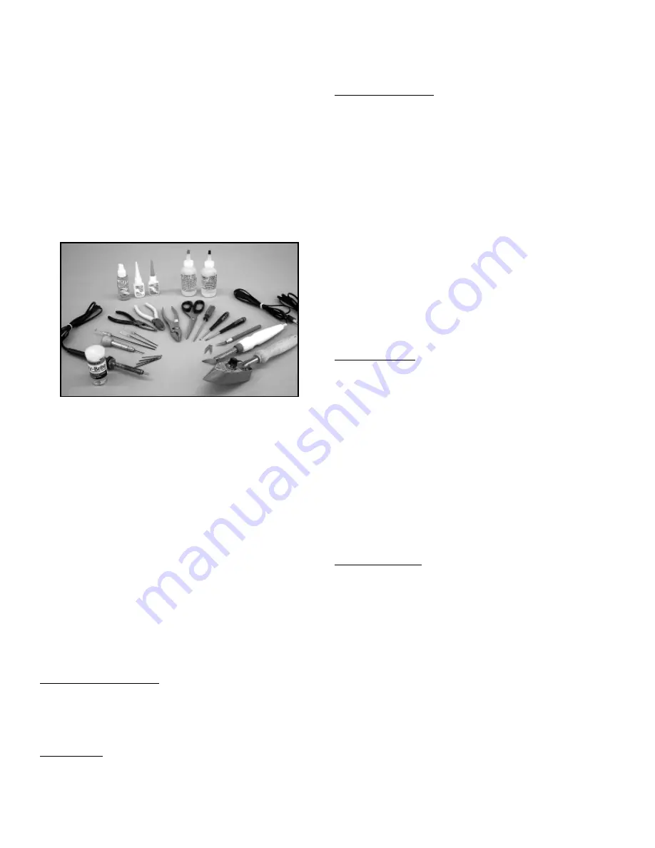
REQUIRED TOOLS:

For proper assembly, we suggest you have the following tools and
materials available:

A selection of glues - SIG Thin and Thick CA and 

SIG Kwik-Set 5-Minute Epoxy

Threadlock Compound, Such as Loctite

®

Non-Permanent Blue

Screwdriver Assortment 
Pliers - Needle Nose & Flat Nose 
Diagonal Wire Cutters 
Small Allen Wrench Assortment 
Pin Vise for Small Dia. Drill Bits 
Hobby Knife With Sharp #11 Blades 
Scissors 
Heat Iron and Trim Seal Tool 
Masking Tape 
Paper Towels 
Small Power Drill With Selection of Bits 
Dremel

®

Tool With Selection of Sanding and Grinding Bits  

A soldering iron and solder.

COMPLETE KIT PARTS LIST:

The following is a complete list of all parts contained in this kit.
Before beginning assembly, we suggest that you take the time to
inventory the parts in your kit.

BASIC AIRCRAFT PARTS:

1 each

Fuselage

1 each

Right & Left Wing Panel Set with Ailerons.

1 each

Horizontal Stabilizer & Elevator Set.

1 each

Vertical Fin & Rudder Set

WIRE PARTS:

1 each

Formed Elevator Joiner Wire

1 each

Formed Tailwheel Wire

2 each

2-56 x 1 1/4” Threaded Rods; servo end of elevator 
& rudder pushrods

2 each

2-56 x 3 1/2” Threaded Rods; control surface end of 
elevator & rudder pushrods

2 each

4-40 x 8” Threaded Rods; aileron pushrods

METRIC HARDWARE:

1 each

M2 x 20mm Phillips Head Screw; for tailwheel 
installation

2 each

M2 Flat Metal Washers; for tailwheel installation

1 each

M2 Hex Nut; for tailwheel installation

1 each

2mm I. D. Wheel Collar with set screw; for tailwheel 
installation

1 each

Allen "L" Wrench; for 2mm wheel collar

3 each

M4 x 16mm Phillips Head Screws; for main landing
gear attachment

4 each

M4 x 22mm Phillips Head Screws; for engine mount 
attachment

2 each

M4 x 30mm Phillips Head Screws; main wheel axles

2 each

M4Hex Nuts; for axles

6 each

M4Flat Metal Washers; (4) for engine mount
(2) for axles

2 each

4mm I. D. Wheel Collars with set screws; for axles

1  each Allen "L" Wrench; for 4mm wheel collars

4 each

#2 x 8mm Phillips head washer style sheet metal 
screws; for canopy

4 each

Nylon "button" washers; for canopy

U.S. HARDWARE:

2 each

1/4-20 x 1-1/2”Nylon Wing Bolts; for wing mounting

1 each

2-56 x 3/4” Threaded Brass Coupler; for carb end of 
throttle pushrod

3 each

2-56 Nylon R/C Links; for  elevator (1), rudder (1), 
throttle (1)

3 each

2-56 Solder R/C Links; for  elevator (1), rudder (1), 
throttle (1)

1 each

Short, Right Nylon Control Horn; for aileron

1 each

Short, Left Nylon Control Horn; for aileron

1 each

Medium, Right Nylon Control Horn; for rudder

1 each

Medium, Left Nylon Control Horn; for elevator

8 each

#2 x 3/4” Sheet Metal Screws; for control horns

2 each

4-40 Metal R/C Links; for aileron (2)

2 each

4-40 Solder R/C Links; for aileron (2)

2 each

4-40 Hex Nuts; for aileron (2)

MISCELLANEOUS:

1 each

12mm Hardwood Front Wing Joiner

1 each

6mm Plywood Rear Wing Joiner

2 each

2mm Plywood Wing Hold-Down Plates

1 each

3mm Plywood Aileron Positioning Guide

1 each

3mm Formed Aluminum Main Landing Gear

1 each

Molded Clear Plastic Canopy

1 set

4pc. Adjustable Engine Mounts, 60-size

22 each CA Hinges; for ailerons (12), elevator (6), rudder (4)

2 each

8.5cm dia. (approx. 3.35”) Main Wheels

1 each

30mm dia. (approx. 1.17”) Tailwheel

1 each

Formed Metal Tailwheel Strap

1 each

2-1/2” dia. Spinner assembly

1 each

10mm sq. X 94mm Balsa; Fuel Tank Retainer

2 each

1cm x 8cm x 20cm Foam Rubber; for radio packing

1 each

2mm x 3.15mm x 26cm Plastic Throttle Pushrod
Tube

1 each

380cc (12.8 oz.) Plastic Fuel Tank with Hardware

1 each

.065" O. D. x 18" Stranded Steel Cable - for throttle 
pushrod

Summary of Contents for FOUR-STAR 60

Page 1: ...ft in your future For reference this assembly manual shows the installation of a Hitec radio system with standard servos In addition you will need two aileron 12 servo lead extensions and a 6 aileron servo Y harness for connection to the receiver ENGINE SELECTION Engine choices for the FOUR STAR 60 ARF are many The FOUR STAR 60 ARF has been designed to produce excellent performance when using the ...

Page 2: ...tion 2 each M2 Flat Metal Washers for tailwheel installation 1 each M2 Hex Nut for tailwheel installation 1 each 2mm I D Wheel Collar with set screw for tailwheel installation 1 each Allen L Wrench for 2mm wheel collar 3 each M4 x 16mm Phillips Head Screws for main landing gear attachment 4 each M4 x 22mm Phillips Head Screws for engine mount attachment 2 each M4 x 30mm Phillips Head Screws main w...

Page 3: ...nges 2 each standard servos 2 each 12 servo extensions 1 each 6 Servo Y Harness for your particular radio system 1 The aileron servo bays are located on the bottom surface of each wing panel These bays have been covered over and now need to be opened to allow access Use a hobby knife to open the aileron servo bay in one wing To make the neatest possible job we suggest cutting each corner of the op...

Page 4: ...ged to the wing panels The installation process for these hinges is the same for all of the control surfaces on this model Press the six CA hinges into the slots in the aileron Use pins in the center of each hinge to keep them centered when pressing them into the slots in the trailing edge of the wing 8 Carefully press the hinges into the trailing edge of the wing Adjust the aileron so that the ti...

Page 5: ...he 4 40 Metal R C Links onto the pushrod so that about 3 8 of the threads on the rod are showing past the barrel of the connector 3 Attach the 4 40 link and pushrod to the second to last hole in the aileron servo output arm Position the pushrod so that it is 90O to the aileron hinge line Use a felt tip pen to mark the pushrod location on the trailing edge of the wing just ahead of the aileron 4 Sw...

Page 6: ...r 1 Slide the front and rear wing joiners into one of the wing panels and then slide the other wing panel into position to test the fit of the joiners The wings should fit tightly together and the center ribs should fit flush around their edges If you need to make any adjustments to get the proper alignment you may slightly trim the openings in the wing ribs 2 Use Sig Slow Cure epoxy to join the t...

Page 7: ...cated on the bottom rear of fuselage 3 Three screw holes for mounting landing gear Located on the bottom of the fuselage just ahead of the wing opening 4 Engine compartment drain hole Located on the bottom of the fuselage just ahead of the firewall Installing the Main Landing Gear For the following step you will need The Fuselage 1 each Formed Aluminum Main Landing Gear 2 each M4 x 30mm Phillips H...

Page 8: ...just the length of the internal silicon fuel tubing to allow free movement of the fuel pick up inside the tank Install the stopper assembly into the neck of the tank and secure by tightening the compression screw ENGINE INSTALLATION This instruction sequence will install both the fuel tank and the engine Therefore you will need the following The Engine with muffler removed not included The Assembl...

Page 9: ... little thread locking compound on all screws when assembling these components The muffler should be mounted after the throttle linkage has been made in the following section 5 Some engine configurations have rear mounted remote needle valve assemblies If you are using this type of engine you will have to likely drill a hole in the side of the fuselage to allow the needle valve to clear Be sure to...

Page 10: ...glued in place in later steps 2 Prepare to install the elevator joiner wire into the inboard leading edges of both elevator halves Start by first removing a strip of covering material over the channel and hole that are already in the leading edges of the elevators for the joiner wire Trial fit the joiner wire Make any small alertations for proper fit 3 Use a toothpick or small dowel to apply epoxy...

Page 11: ...er is now glued in place into the rear of the fuselage We suggest using 5 minute epoxy for this job to allow time to position the stab accurately and make any final adjustments that might be needed Allow the glue to set completely 9 The elevators are now hinged to the stabilizer Use the same hinging method described earlier in Step 8 of the WING ASSEMBLY instructions 10 Place the fin into position...

Page 12: ... little play in the wheel and use the Allen wrench to tighten and secure the wheel collar to the axle A little thread locking compound on the set screw will keep it firmly in place 15 The tailwheel assembly is now mounted to the bottom front of the rudder Use your hobby knife to remove the covering from the slot in the bottom of the rudder 16 Insert the upright tailwheel wire stub into the hole an...

Page 13: ...the 2 56 solder links 2 Insert the unthreaded end of the 3 1 2 control rod into one of the 36 nylon control tubes up to the threads on the rods Thread the rod into the tube about 3 16 1 4 Repeat this procedure with the remaining tube and rod Thread a nylon R C link onto the exposed threads of each rod these are the ends that will be attached to the rudder and elevator control horns 3 Start with th...

Page 14: ... for the required solder connection 8 Remove the cable and cut it at the mark just made use a carbide cut off wheel for this cut and reinsert it back into the throttle housing tube in the face of the firewall Solder the link in place to the trimmed end of the cable Connect the solder link to the servo output arm and the nylon R C link to the carburetor throttle arm Use the radio to test the thrott...

Page 15: ...RIGHT THROTTLE FULL RANGE OF TRAVEL NOTE These measurements were taken as follows Elevator travel measured at the widest inboard trailing edge Aileron travel measured at the inboard trailing edge Rudder travel measured at the widest lower trailing edge DECAL APPLICATION The decals supplied with your FOUR STAR 60 ARF are high quality Mylar with an extremely aggressive adhesive These are not die cut...

Page 16: ...once As the FOUR STAR 60 ARF begins moving forward back off of the up elevator input and use the rudder as needed to correct any engine torque and or wind induced deviations from a straight take off run At takeoff speed use a slight amount of up elevator to lift off using ailerons to keep the wings level Climb to a reasonable altitude before making any trim changes Although not intended as a train...

Page 17: ...of any form either model size or full size are not toys Because of the speeds that airplanes must achieve in order to fly they are capable of causing serious bodily harm and property damage if they crash IT IS YOUR RESPONSIBILITY AND YOURS ALONE to assemble this model airplane correctly according to the plans and instructions to ground test the finished model before each flight to make sure it is ...

Page 18: ...18 R ...

Reviews: