background image


4115102 

Rev 1.1 

February 21, 2014 

12 

3.  Handling 

3.1. 

Storage of the AirPrime Snap-in Socket  

3.1.1. 

Storage Condition 

AirPrime Snap-in socket can be stored in their original packages, over the course of up to 1 year.  

They can withstand a storage temperature range between -40°C to +85°C, nevertheless when packed 
into T&R the upper storage temperature is decreased to +40°C due to T&R packaging material. 

Tip:  

For optimal results, the recommended storage temperature is +20°C +/- 10 degrees.  

3.2. 

Component Package 

3.2.1. 

Package Description 

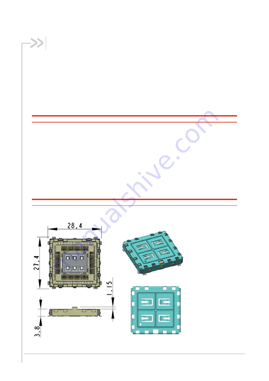
The AirPrime Snap-in socket is a scalable QFP 27.4x28.4 mm, pitch 0.8 mm. 

Height with the cover assembled: 4.9 ±0.2 mm. 

Number of contacts:  66 Pins  

Weight: Snap-in socket with cover 2.5 mm: 4.7 g (TBC) 

Note:  

The AirPrime Snap-in socket if for use with the AirPrime HL Series modules. 

For additional information, refer to the product technical specifications listed in section 1.2 Reference 
Documents.


Figure 3. 

AirPrime Snap-in Socket 

Summary of Contents for AirPrime HL Series

Page 1: ...4115102 1 1 February 21 2014 AirPrime HL Series Snap in Socket Customer Process Guidelines...

Page 2: ...the aircraft is on the ground and the door is open Sierra Wireless modems may be used at this time The driver or operator of any vehicle should not operate the Sierra Wireless modem while in control...

Page 3: ...red trademarks of Sierra Wireless Inc or one of its subsidiaries Watcher is a registered trademark of NETGEAR Inc used under license Windows and Windows Vista are registered trademarks of Microsoft Co...

Page 4: ...ry 21 2014 4 Customer Process Guidelines Document History Version Date Updates 1 0 February 19 2014 Creation 1 1 February 21 2014 Updated Figure 12 AirPrime Snap in Socket Removal Tool Figure 13 Snap...

Page 5: ...12 3 1 1 Storage Condition 12 3 2 Component Package 12 3 2 1 Package Description 12 3 3 Component Packing 13 3 3 1 Packing Description 13 3 3 2 Packing Label 13 4 SMT ASSEMBLY PROCESS 14 4 1 Lead Free...

Page 6: ...p in Socket Footprint Recommendation Copper Layout Position 15 Figure 7 AirPrime Snap in Socket Footprint Recommendation Copper Layout 16 Figure 8 AirPrime Snap in Socket Footprint Recommendation Sold...

Page 7: ...ents guidelines for the industrial assembly of the AirPrime Snap in Socket on an application 1 2 Reference Documents 1 AirPrime HL6528x Product Technical Specification Reference number 4114016 2 AirPr...

Page 8: ...e given under the following atmospheric conditions Ambient temperature 5 C to 35 C Relative humidity 45 RH to 85 RH Air pressure 86kPa to 106kPa 2 4 Electrical Characteristics The tests are performed...

Page 9: ...cket Characteristics 2 5 Mechanical Characteristics Items Conditions Specifications Appearance No defects such as cracks scratches or blemishes Terminal retention force The retention force when the te...

Page 10: ...4115102 Rev 1 1 February 21 2014 10 Customer Process Guidelines Snap in Socket Characteristics 2 5 1 Mechanical Drawings Figure 1 Snap in Socket Diagram...

Page 11: ...4115102 Rev 1 1 February 21 2014 11 Customer Process Guidelines Snap in Socket Characteristics Figure 2 Snap in Socket Cover Diagram...

Page 12: ...T R packaging material Tip For optimal results the recommended storage temperature is 20 C 10 degrees 3 2 Component Package 3 2 1 Package Description The AirPrime Snap in socket is a scalable QFP 27...

Page 13: ...is 450 AirPrime Snap in frames and 450 covers The inner packaging is different for the frame and for the cover as shown in the figures below The frame of the Snap in socket is delivered in tape and r...

Page 14: ...g hazardous substances mercury Hg lead Pb cadmium Cd hexavalent chromium Cr 6 polybrominated diphenyl ether PBDE polybrominated biphenyl PBB The AirPrime snap in sockets are manufactured with RoHS com...

Page 15: ...ket Footprint Recommendation Copper Layout Position In order to produce high assembly yields and a reliable solder joint the footprint design should match Figure 7 below This footprint is compatible f...

Page 16: ...igure 7 AirPrime Snap in Socket Footprint Recommendation Copper Layout Note The 64 inner pads and the 8 corner pads are ground pads Sierra Wireless suggests that customers place a copper pad under the...

Page 17: ...m 4 3 Solder Mask The pads on the printed circuit board are either Solder Mask Defined SMD or Non Solder Mask Defined NSMD Since the copper etching process has tighter control than solder masking pro...

Page 18: ...1 February 21 2014 18 Customer Process Guidelines SMT Assembly Process Figure 8 AirPrime Snap in Socket Footprint Recommendation Solder Mask Layout Recommended solder mask thickness on the top copper...

Page 19: ...l thickness is 125 m The proposed stencil design is presented in Figure 9 below This stencil is compatible for both soldering the module on its own and for soldering a Snap in Socket It is highly reco...

Page 20: ...4115102 Rev 1 1 February 21 2014 20 Customer Process Guidelines Board Mounting Guidelines Figure 9 AirPrime Snap in Socket Footprint Recommendation Paste Mask Layout...

Page 21: ...Profile Lead free SMT reflow profiles should be used to surface mount the AirPrime Snap in socket The reflow profile depends on PCB density and type of solder paste being used The paste manufacturer...

Page 22: ...delines Additional recommendations are presented in the table below for consideration Factor Recommendation Max slope 2 to 4 C sec Soak time between A and B 150 and 190 C 60 to 120 sec Reflow time D o...

Page 23: ...dule and the Snap in socket 2 Put the module down in the socket Use vertical motion to insert the module 3 Check the orientation of the cover based on the location of Pin 1 Pin 1 location on the Snap...

Page 24: ...cess Guidelines Insertion and Removal Guidelines 4 Smoothly press the cover on to the Snap in socket The cover should be properly aligned with Pin 1 of the module 5 Check that the cover holes are lock...

Page 25: ...e 12 AirPrime Snap in Socket Removal Tool To dismount the cover from the Snap in socket insert the Snap in removal tool in the socket cavity and then smoothly push the tool to pull up the cover and di...

Page 26: ...result in contact damage Inserting removing the module incorrectly would result in contact damage Note Only use vertical motion to insert and or remove the module Do not apply force onto the heat sin...

Page 27: ......

Reviews: