


Rev 3 Sep.18
15
41112607
4
4: Interfaces Specification
4.1 Overview
This section describes the interfaces supported by the AirPrime BX310x embedded
module and provides specific voltage, timing, and circuit recommendations for each
interface.
4.2 UART
The AirPrime BX310x provides one UART interface for asynchronous communication
between the AirPrime BX310x module and a host device (e.g. a PC or host
processor):
•
UART0—4-wire, RS-232-compliant interface
Note: Up to two additional UART interfaces can be added by configuring GPIOs using AT
commands.
Flow control is managed using:
•
RTS/CTS signals (This method is required for higher UART interface speeds.)
or
•
Software XON/XOFF
describes the signals used for UART0.
Note: UART signals are named with respect to the HOST, and directions are listed with respect
to the module. For example, UART0_RXD is an output from the module to the host.
The UART interface is configurable via AT commands:
•
Default configuration—115200 (baudrate), 8 bit, no parity, no handshaking
•
Baudrate considerations:
·
Maximum supported—5 Mbaud
·
Maximum tested—3 Mbaud. This is the maximum baudrate supported by the
BX310x Dev Kit FTDI converter IC.
·
HW handshaking is recommended above rates of 1 Mbaud and can be
enabled via AT command (AT&K3).
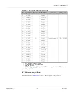
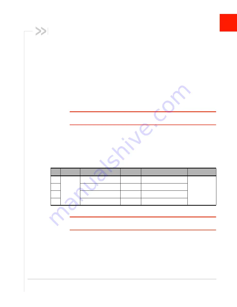
Table 4-1: UART0 Pins
a
Pin
Interface
Name
Direction Function
Voltage Level
2
UART0
UART0_RTS
I
Ready To Send, flow control
VDD_PADS_BB
3
UART0_CTS
O
Clear To Send, flow control
4
UART0_TXD
I
Transmit Data
5
UART0_RXD
O
Receive Data
a. If UART0 pins are not used, leave open.