


Hardware Integration Guide
Rev 3 Sep.18
28
41112607
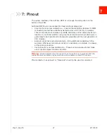
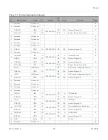
7.1 Pin Configuration
illustrates the pin configuration of the AirPrime BX310x module.
Figure 7-1: Pin Configuration (Bottom View)
7.2 Pin Description
lists detailed information for the LGA pins.
Important:
Leave open all pins that are not used.
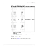
Table 7-1: Pin Definitions
Pin
Signal name
Group
I/O
a
Voltage
PU/
PD
b
Active
c
Function
Type
d
1
Reserved
NoConnect
-
-
-
-
E
2
UART0_RTS_GPIO(22)
UART0
I
VDD_PADS_BB
PU
L
UART0 Request To Send
C
3
UART0_CTS_GPIO(19)
UART0
O
VDD_PADS_BB
PU
L
UART0 Clear To Send
C
4
UART0_TXD
UART0
I
VDD_PADS_BB
PU
L
UART0 Transmit Data
C
5
UART0_RXD
UART0
O
VDD_PADS_BB
PU
L
UART0 Receive Data
C
6
Reserved
NoConnect
-
-
-
-
-
E


