


Installation
4.9 Installing and removing the shaft-mounted gearbox
BA 2012
Operating Instructions, 03/2013, 70000004024300
27
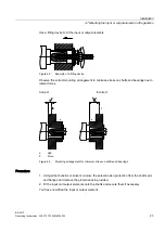
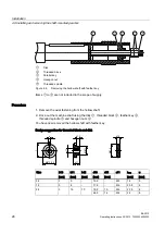
3.
Use a nut
③
and threaded spindle
④
to fit the gearbox. The counterforce is provided by
the hollow shaft
②
.
4.
Replace the nut
③
and threaded spindle
④
with a setscrew and tighten it with the
specified torque.
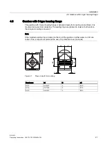
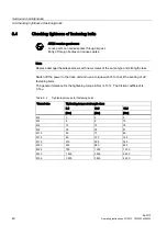
Table 4- 2
Tightening torque for setscrews
Thread size
M5
M6
M8
M10
Tightening torque [Nm]
5
8
8
14
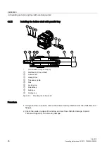
4.9.3
Removing the hollow shaft with parallel key
WARNING
Inadequately secured gearbox or geared motors can free themselves and fall
Before driving out the machine shaft, fasten a suitably dimensioned means of absorbing
load to the gearbox.
Slightly pretension the drive element so that the gearbox does not drop into the drive
element when the insert shaft is released.
NOTICE
Misalignment of and stress on the hollow shaft can lead to excessive load and cause the
bearings to fail
It is essential to prevent misalignment when removing the unit.
Note
If frictional corrosion has occurred on the seat surfaces, use rust solvent to facilitate the
removal of the gearbox. Allow the rust solvent to work in sufficiently.
Summary of Contents for Worm Gearbox S 5 BA 2012
Page 1: ...Answers for industry MOTOX MOTOX Worm Gearbox S BA 2012 Operating Instructions 03 2013 ...
Page 2: ......
Page 34: ...Commissioning BA 2012 32 Operating Instructions 03 2013 70000004024300 ...
Page 36: ...Operation BA 2012 34 Operating Instructions 03 2013 70000004024300 ...
Page 44: ...Disposal BA 2012 42 Operating Instructions 03 2013 70000004024300 ...
Page 53: ......