background image

Installation 


4.2 General information on installation 


BA 2012 

18


Operating Instructions, 03/2013, 70000004024300 


NOTICE 


Overheating of the gearbox due to exposure to direct sunlight 
Provide suitable protective equipment such as covers or roofs. Prevent heat accumulation. 


NOTICE 


Malfunction resulting from foreign objects 
The operator must ensure that no foreign objects impair the function of the gearbox. 


NOTICE 


Exceeding the permissible oil sump temperature due to incorrect settings of temperature 

monitoring equipment 
An alarm must be output when the maximum permissible oil sump temperature is reached. 

The geared motor must be switched off when the maximum permissible oil sump 

temperature is exceeded. This switching off can cause plant shutdown. 


Note 
Use headless screws of strength class 8.8 or higher to fasten the gearbox. 


Exercise particular care during mounting and installation. The manufacturer cannot be held 

liable for damage caused by incorrect mounting and installation. 
Make sure that there is sufficient space around the gearbox or geared motor for mounting, 

maintenance and repair. 
On geared motors with a fan, leave sufficient free space for the entry of air. Observe the 

installation conditions for the geared motor. 
Provide sufficient lifting gear at the start of mounting and fitting work. 

Summary of Contents for Worm Gearbox S 5 BA 2012

Page 1: ...Answers for industry MOTOX MOTOX Worm Gearbox S BA 2012 Operating Instructions 03 2013 ...

Page 2: ......

Page 3: ...________________ ___________________ General information and safety notes 1 2 Technical description Incoming goods transport and storage 3 MOTOX 4 Installation Worm Gearbox S 5 BA 2012 Commissioning 6 Operation Operating Instructions Faults causes and remedies 7 Service and maintenance 8 9 Disposal 10 Technical data 11 Spare parts Declaration of Incorporation Declaration of Conformity 12 03 2013 7...

Page 4: ... only by personnel qualified for the specific task in accordance with the relevant documentation in particular its warning notices and safety instructions Qualified personnel are those who based on their training and experience are capable of identifying risks and avoiding potential hazards when working with these products systems Proper use of Siemens products Note the following WARNING Siemens p...

Page 5: ...htening torque for fastening bolts on the gearbox 19 4 4 Gearbox with foot mounting 20 4 5 Gearboxes in foot or flange version 20 4 6 Gearbox with C type housing flange 21 4 7 Mounting the input or output element on the gearbox 22 4 8 Removing and installing the protection cover 24 4 9 Installing and removing the shaft mounted gearbox 25 4 9 1 General information on installing the shaft mounted ge...

Page 6: ...Check gearbox for leaks 38 8 3 Cleaning the gearbox or geared motor 39 8 4 Checking tightness of fastening bolts 40 9 Disposal 41 10 Technical data 43 10 1 General technical data 43 10 2 Weight 45 10 3 Types of construction 46 11 Spare parts 47 12 Declaration of Incorporation Declaration of Conformity 49 12 1 Declaration of Incorporation 49 12 2 EC Declaration of Conformity 50 ...

Page 7: ...erating instructions near the gearbox These operating instructions apply to the standard version of the MOTOX worm gearbox S in sizes 08 18 and 28 Table 1 1 Order number code Structure of the order number position MOTOX gearbox 1 2 3 4 5 Worm gearbox S 2 K J 1 7 Note In addition to these operating instructions special contractual agreements and technical documentation apply to special gearbox desi...

Page 8: ...49 0 911 895 7222 Fax 49 0 911 895 7223 America USA Phone 1 42 32 62 25 22 Asia China Phone 86 10 64 75 75 75 E Mail support automation siemens com Internet German http www siemens de automation support request Internet English http www siemens com automation support request Applicable operating instructions Table 1 2 MOTOX gearbox operating instructions Title Product BA 2010 MOTOX Gearbox BA 2011...

Page 9: ...eneral machine engineering applications Unless otherwise agreed the gearboxes have been designed for use in machinery and plants in industrial environments The gearboxes have been built using state of the art technology and are shipped in an operationally reliable condition Changes made by users could affect this operational reliability and are forbidden Note The performance data assumes an ambien...

Page 10: ...hat work is in progress on the geared motor Carry out all work with great care and with due regard to safety For all work observe the relevant regulations for work safety and environment protection Read the instructions on the rating plates attached to the geared motor The rating plates must be kept free from paint and dirt at all times Replace any missing rating plates In the event of changes dur...

Page 11: ...ulations and directives by electrotechnology specialists Do not use high pressure cleaning equipment or sharp edged tools to clean the gearbox Observe the permissible tightening torque of the fastening bolts Replace damaged bolts with new bolts of the same type and strength class Siemens AG accepts the warranty only for original spare parts The manufacturer who installs the geared motors in a plan...

Page 12: ...ot escaping oil Before starting any work wait until the oil has cooled down to below 30 C WARNING Poisonous vapors when working with solvents Avoid breathing in vapors when working with solvents Ensure adequate ventilation WARNING Risk of explosion when working with solvents Ensure adequate ventilation Do not smoke WARNING Risk of eye injury Rotating parts can throw off small foreign particles suc...

Page 13: ...agreement 2 2 Cooling NOTICE High housing temperature Dust deposits prevent heat radiation and cause high housing temperatures Keep the gearbox free from dirt and dust etc The gearbox does not normally require additional cooling The generously dimensioned housing surface is sufficient for dissipating heat losses where there is free convection If the housing temperature exceeds a value of 80 C plea...

Page 14: ...is not painted The gearbox is optionally delivered complete with primer and paint finish ATEX version gearboxes When applying conductive paint the operating company must ensure that the paint remains in a perfect state The paint finish must be checked at intervals of approximately 2 3 years ATEX version gearboxes An excessively high electrostatic charge must be avoided Ensure that highly active me...

Page 15: ...diately on arrival for completeness and any transport damage Notify the freight company of any damage caused during transport immediately this is the only way to have damage rectified free of charge Siemens AG will not accept any claims relating to items missing from the delivery and which are submitted at a later date The gearbox or geared motor is delivered in a fully assembled condition Additio...

Page 16: ...ctivate them again Different forms of packaging may be used depending on the size of the gearbox or geared motor and the method of transport Notwithstanding contractual agreements to the contrary the packaging complies with HPE Packaging Guidelines Bundesverband Holzpackmittel Paletten Exportverpackungen e V the German Federal Association for wooden packaging means pallets and export packaging Not...

Page 17: ...ids alkalis sparks welding beads and heat cause corrosion Do not damage the paint finish Unless contractually agreed otherwise the guarantee period for the standard preservative lasts 6 months from the date of delivery In the case of storage in transit over 6 months special arrangements must be made for preservation Please contact Technical Support Store the gearbox or geared motor in dry dust fre...

Page 18: ...Incoming goods transport and storage 3 3 Storage BA 2012 16 Operating Instructions 03 2013 70000004024300 ...

Page 19: ...currents from electrical equipment When mounting the gearbox on or connecting it to the machine take care to ensure potential equalization The information on grounding and equipotential bonding provided by the motor supplier must be observed WARNING Uncontrolled starting or reversing of the system under load The entire system must be load free so that there is no danger during this work NOTICE Irr...

Page 20: ...e maximum permissible oil sump temperature is reached The geared motor must be switched off when the maximum permissible oil sump temperature is exceeded This switching off can cause plant shutdown Note Use headless screws of strength class 8 8 or higher to fasten the gearbox Exercise particular care during mounting and installation The manufacturer cannot be held liable for damage caused by incor...

Page 21: ...ot be used in some cases due to a lack of space In such cases please contact Technical Support quoting the type of gearbox 4 3 Tightening torque for fastening bolts on the gearbox The general tolerance for the tightening torque in Nm is 10 The friction coefficient is 0 14 μ Table 4 1 Tightening torques for fastening bolts Tightening torque at strength class 8 8 10 9 12 9 Thread size Nm Nm Nm M4 3 ...

Page 22: ...t which cannot be measured at a standstill When using foundation blocks to fasten the gearbox to a concrete foundation suitable recesses should be made in the foundation Align and grout the slide rails into the foundation Align the gearbox carefully with the units on the input and output side Take into account the elastic deformation due to operating forces Prevent displacement from external force...

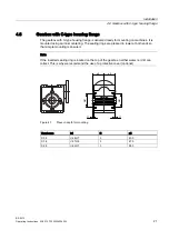
Page 23: ...chines It is mounted using an inner centering The sealing rings are pressed in lower at both ends so that simple mounting is ensured Note If the inserted sealing ring is located on the top of the gearbox neither water nor dirt can collect This is why we recommend the use of a protective cover optional E E I I R R Figure 4 1 Press in depth for mounting Gearboxes b1 f1 o5 S 08 48 H7 3 40 0 S 18 47 H...

Page 24: ...ent errors caused by excessive angle or axial displacement of the shaft ends to be joined lead to premature wear or material damage Ensure precise alignment of the individual components NOTICE Damage to bearings housing shaft and locking rings due to improper handling Do not use impacts or knocks to force the input and output elements to be mounted onto the shaft Note Deburr the parts of elements ...

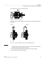
Page 25: ...ment to minimize stress on shafts and bearings due to lateral forces Correct Incorrect D D a Hub F Force Figure 4 3 Mounting arrangement for minimum stress on shafts and bearings Procedure 1 Using either benzine or solvent remove the anti corrosion protection from the shaft ends and flanges and remove the protective skin provided 2 Fit the input and output elements onto the shafts and secure them ...

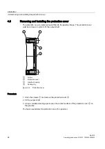
Page 26: ...the gearbox flange The protection cover must be removed in order to fit the output shaft o r i o r i Screw Protection cover Gearbox housing Sealing ring Figure 4 4 Protection cover Procedure 1 Undo the screws and remove the protection cover 2 Fit the output shaft 3 Using a suitable cleaning agent clean the contact surface of the protection cover on the gearbox You have now installed the protection...

Page 27: ...s NOTICE Misalignment of and stress on the hollow shaft can lead to excessive load and cause the bearings to fail The hollow shaft must be flush with the machine shaft to avoid misalignment Do not subject the hollow shaft to axial and radial stress Note To prevent frictional corrosion and to facilitate installation apply a suitable lubricant to the contact surfaces e g Klüberpaste 46MR401 Note Obs...

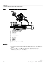
Page 28: ...e of supply Machine shaft nsert shaft Hollow shaft Hexagon nut Threaded spindle Disk Locking ring Parallel key Setscrew Sealing cap Figure 4 5 Mounting the hollow shaft Procedure 1 Using benzine or a solvent remove the anti corrosion protection from the shaft ends and flanges 2 Check the seats or edges of the hollow and machine shafts for damage Contact Technical Support if you notice any damage ...

Page 29: ... key WARNING Inadequately secured gearbox or geared motors can free themselves and fall Before driving out the machine shaft fasten a suitably dimensioned means of absorbing load to the gearbox Slightly pretension the drive element so that the gearbox does not drop into the drive element when the insert shaft is released NOTICE Misalignment of and stress on the hollow shaft can lead to excessive l...

Page 30: ...ncluded in the scope of supply Procedure 1 Remove the axial fastening from the hollow shaft 2 Drive out the machine shaft using the disk threaded block feather key threaded spindle and hexagon nuts You have now removed the hollow shaft with feather key Design suggestion for threaded block and disk G V G E G E E X W b10 b11 b12 d10 d11 tmax u Size mm mm mm mm mm s11 mm mm 08 3 5 15 9 M5 18 5 18 3 6...

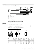
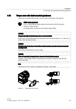
Page 31: ...OTICE Dangerously high transient torques due to excess backlash Take care to prevent the torque arm causing excessive constraining forces e g due to the driven shaft running out of true NOTICE Misalignment of and stress on the hollow shaft can lead to excessive load and cause the bearings to fail Do not tension torque arms when mounting NOTICE Worn or irreparably damaged rubber elements will not f...

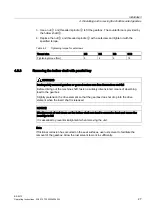
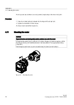
Page 32: ... Tighten the bolts M6 to 10 Nm torque You have now mounted the torque arm 4 11 Mounting the motor NOTICE If geared motors are inadequately sealed moisture can enter the motor If installing the geared motor outdoors or if a higher degree of protection applies IP55 the flange screws and installed elements must be sealed with an appropriate sealing compound The flange mounted motor must be sealed acr...

Page 33: ...eat to the environment and health Remove any oil spillage immediately with an oil binding agent in compliance with environmental requirements Procedure After mounting the geared motor is ready for use 1 Run the geared motor for a short period of time under no load operation 2 Check for any irregularities such as oil leakages strong vibration and noise 3 Switch in the load You have now started up t...

Page 34: ...Commissioning BA 2012 32 Operating Instructions 03 2013 70000004024300 ...

Page 35: ...on of possible incipient damage CAUTION Faults can cause damage to the gearbox or personal injuries In the event of changes during operation the drive unit must be switched off immediately Use the fault table in the section titled Faults causes and remedies to determine the cause of the fault Remedy faults or have faults remedied Check the gearbox during operation for Excessive operating temperatu...

Page 36: ...Operation BA 2012 34 Operating Instructions 03 2013 70000004024300 ...

Page 37: ...es Faults Causes Remedy Excessive bearing play and or bearing defective Check bearing and replace if necessary Unusual noises from gearbox Teeth defective Check teeth and replace if necessary Fastening bolts loose Tighten bolts nuts see Checking tightness of fastening bolts Page 40 Excessive external load on drive input and output Check load against rating data Damage in transit Check the gearbox ...

Page 38: ...or damage in transit Oil leak Frequent cold starts during which the oil foams up Call Technical Support Motor fan cover and or gearbox heavily soiled Clean the fan cover and surface of the geared motor see Cleaning the gearbox or geared motor Page 39 Excessive bearing play and or bearing defective Check bearing and replace if necessary Gearbox overheating Power or speed too high Adhere to data on ...

Page 39: ...ined and authorized personnel Only original parts supplied by Siemens AG can be used for servicing and maintenance Note The gearbox is lubricated for life Lubricant changes are not required All inspection maintenance and repair work must be carried out with care by trained personnel only Observe the information in Section General information and safety notes Page 5 Table 8 1 Maintenance measures M...

Page 40: ...aping are significant or leaking continues after the running in phase the shaft sealing ring must be replaced to prevent consequential damage Shaft sealing rings are subject to natural wear The service life depends on the operating conditions We recommend that shaft sealing rings are included in periodic maintenance and servicing work on the system Leakage no leaks Table 8 2 Description and measur...

Page 41: ...revent heat radiation and cause high housing temperatures Keep the geared motor free from dirt and dust NOTICE Cleaning with high pressure cleaning equipment can cause water to enter the gearbox Seals can be damaged Do not use a high pressure cleaning appliance to clean the geared motor Do not use tools with sharp edges Switch off the power supply to the drive unit before cleaning it ...

Page 42: ...s of the same type and strength class Switch off the power to the drive unit and use a torque wrench to check the seating of all fastening bolts The general tolerance for the tightening torque in Nm is 10 The friction coefficient is 0 14 μ Table 8 3 Tightening torques for fastening bolts Tightening torque at strength class 8 8 10 9 12 9 Thread size Nm Nm Nm M4 3 4 5 M5 6 9 10 M6 10 15 18 M8 25 35 ...

Page 43: ...l 4 VI Used Oil Collect and dispose of used oil in accordance with regulations Remove oil spillages immediately with an oil binding agent in compliance with environmental requirements Dispose of the housing parts gears shafts and roller bearings of the geared motor as steel scrap The same applies to grey cast iron parts if no separate collection is made The worm wheels are made partly from non fer...

Page 44: ...Disposal BA 2012 42 Operating Instructions 03 2013 70000004024300 ...

Page 45: ... 5 6 2 1 8 50Hz 50Hz 29 16 74A 15kW IE1 90 cosPhi 0 84 28 6A 60Hz 100Nm 190 240V AC 460V Y cosPhi 0 87 1460 min 15kW 1755 min 400 690V 1266Nm 3 Mot ThCl 155 F TP PTC D Y 113 min fB 1 5 1264Nm fB 1 5 KAF108 LA160L4 L150 100GH 2KJ1506 5JR13 2FD1 Z IP55 G 6 2L OIL CLP PG VG220 i 12 9 60Hz 136 min FDU1001 8999999 nnn 254kg IEC60034 IM H 01 A Figure 10 1 Rating plate example 1 CE marking or other marki...

Page 46: ... protection TP 24 Symbols IEC 60617 2 brake 25 Braking torque TBr Nm 26 Brake supply voltage U V Frequency 1 27 Rated frequency f Hz 28 Rated voltage range U V 29 Circuit graphical symbols as per DIN EN 60617 Part 6 IEC 60617 6 30 Rated current I A 31 Power factor cos φ 32 Rated output P kW mode if S1 33 Efficiency class designation 34 Rated speed n1 rpm Frequency 2 35 Rated frequency f Hz 36 Rate...

Page 47: ...ssion ratio i Frequency 1 13 Rated frequency f Hz 14 Speed at output n2 rpm 15 Torque at output T2 Nm 16 Service factor fB Frequency 2 17 Rated frequency f Hz 18 Speed at output n2 rpm 19 Torque at output T2 Nm 20 Service factor fB 21 Explosion hazard symbol and explosion hazard marking Figure 10 2 ATEX rating plate 10 2 Weight The weight of the entire geared motor is given in the shipping papers ...

Page 48: ...e compliant with IEC 60034 7 Code I The lubrication for life has been designed to enable the gearbox to be operated in all the types of construction and mounting positions shown 6 6 6 6 0 0 6 6 6 6 0 0 6 6 6 6 0 0 6 6 6 6 0 0 6 6 6 6 9 0 9 9 0 9 6 6 6 6 9 0 9 9 0 9 A B Position of insert shaft solid shaft Figure 10 3 Type of construction options for S sizes 08 18 28 ...

Page 49: ...upply spare parts which meet state of the art technical standards and comply with the latest legal requirements Please state the following data when ordering spare parts Serial no see rating plate Type designation see rating plate Part no 3 digit item no from spare parts list 6 digit code no or 7 digit article no Quantity SIEMENS SIEMENS 13 27 30 32 31 38 35 25 26 36 37 39 34 33 40 41 42 28 15 21 ...

Page 50: ...004024300 001 Gearbox housing 040 Flange 045 Screw 090 Torque arm 095 Screw 201 Flange 205 Screw 210 Screw 401 Insert shaft 402 Parallel key 403 Parallel key 411 Screw 412 Disk 413 Disk 415 Locking ring 418 Sealing cap Figure 11 2 Worm gearbox S sizes 08 18 28 ...

Page 51: ...5 5 1 5 6 1 5 8 1 5 9 1 5 10 1 5 11 1 5 13 1 5 15 1 6 1 1 6 2 1 7 1 1 7 1 1 1 7 2 1 7 3 1 7 4 1 7 4 1 1 7 4 2 1 7 4 3 The partly completed machine may only be commissioned once it has been established if applicable that the machine in which the partly completed machine is to be incorporated meets the provisions of Directive 2006 42 EC The manufacturer is obligated to transmit the special technical...

Page 52: ...II2 G D IIB ck T4 120 C II2 G D IIC ck T4 120 C II2 G D IIB bck T4 120 C II2 G D IIC bck T4 120 C II3 G D IIB ck T4 120 C II3 G D IIC ck T4 120 C The specific marking of the gearbox is noted on the rating plate EC Declarations of Conformity and or EC type examination certificates for further equipment added to the gearbox and or for safety systems are enclosed e g for Rotating electrical machines ...

Page 53: ......

Page 54: ...vetechnology Subject to change without prior notice Siemens AG 2013 Siemens AG Industry Sector Mechanical Drives Postfach 1709 72007 TÜBINGEN GERMANY MOTOX in the Internet www siemens com gearedmotors Further information ...

Reviews: